Transcription of British Signalling – What the driver sees v2
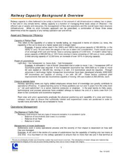
1 Railway Technical Website Background Paper No. 1 British Signalling what the driver sees by Piers Connor1 Introduction This page describes the types of signals seen on British railways and their meanings. Semaphore and colour light signals are included. Semaphore Signals During the 19th century a system of mechanically operated semaphore signals was developed for Britain's railways . Although there were many different and independent railway companies, by the early 20th century, signals were generally standardised, but with some variations in style and appearance. Many semaphore signals have survived to this day, although they are becoming rarer.
2 However, there are some excellent examples still to be seen on the heritage lines operated by preservation groups all over the country. Semaphore Signal Parts First, a diagram (left) of a semaphore signal and its main parts. The signal is normally placed on the left side of the track with the arm directed over the offside. The standard arm is red with a white vertical band, although some older signals were plain red. To allow the signal indication to be seen at night, the arm is fitted with two lenses, duplicating the indication displayed. The lenses are illuminated from behind, originally by oil lamps, later by electric lamps.
3 The signal is mounted on a signal post, originally wooden but later lattice steelwork, pressed steel, old rail, and concrete appeared at various places. Some railways could be recognised from the design of their signal posts, the ones from the Victorian era having elaborate finials and other attachments. Signal posts were often tall, so that the signal could be seen clear of engine smoke and from a distance. It was also intended that the guard could see the signal from the rear of the train as it was part of his duties to check signal indications. 1 PRC Rail Consulting Ltd. One of a series of papers originally published as pages on RTWP and updated for RTW.
4 Background Paper Basic Railway Signalling Railway Technical Website Page 2 Updated 11th December 2017 The post is normally fitted with a ladder, originally to allow access to the oil lamps and now retained for maintenance. The post is often provided with a telephone linked to the signal box. The telephone is contained in a small box with black and white diagonal stripes on the cover. The driver or other train crew can use this to alert the signalman of the presence of the train and to enquire why the signal remains "at danger", as we say in the trade. The arm of the signal is displayed in a horizontal position to show the "stop" or "danger" indication.
5 The red lens is illuminated. The indication to the driver is "stop" until either the signal indication gives "proceed" or he is given verbal authority by the signalman to proceed. To give a "proceed" indication, the semaphore arm is raised to an angle of 45 as shown in the diagram. The movement of the arm causes the green lens to replace the red lens in front of the lamp. A "proceed" indication tells the driver that he may proceed at normal speed for that section of line, subject to any speed restrictions displayed and according to the speed limit of the particular type of train he is driving. Unlike many other countries, British signals do not give a speed indication to the driver .
6 Some signals showed "proceed" by lowering the arm instead of raising it. This type of signal is called a "lower quadrant semaphore", (shown as an inset in the diagram) as opposed to the more usual "upper quadrant" type. The lower quadrant type was much favoured by the Great Western Railway but eschewed by others following an accident caused by a stop signal showing a proceed indication because it drooped with the weight of snow resting on the arm. The GWR maintained they had never had an accident caused by this type of signal so they weren't about to change them now. Anyway, they didn't want the expense. One final part of the signal mechanism is the balance weight.
7 It is linked to the cable which operates the signal. The cable, of course, is connected to the lever in the signal box which operates that particular signal. The purpose of the balance weight is to pull back the signal wire when the lever is replaced in the frame by the signalman. Types of Semaphore Signal The following series of diagrams, with descriptions, shows the various types of semaphore signals seen in the UK. A Home Signal or Starting Signal (left) is the stop signal described above. It is placed at the entrance to a block and, when showing "stop", the train is forbidden to enter the block. When a signal shows a stop or other restrictive indication, it is said to be "on".
8 A signal showing a proceed indication is said to be "off . Traditionally, at a station, each track would have two stop signals. One, protecting the entrance to the block, was called the Home Signal. The other, protecting the exit towards the next station or signal box, was called the Starting Signal or Starter. As mentioned above, this is a stop signal showing a proceed indication - it is "off". The train may enter the block at normal speed. In effect, this means the maximum speed applicable to this section of line and the type of train. To give advanced warning of the indication of a stop signal, a "distant" signal is sometimes provided (left).
9 This operates in the same way as the stop signal but gives either a "caution" indication (it is said to be Background Paper Basic Railway Signalling Railway Technical Website Page 3 Updated 11th December 2017 "on"), shown on the left, or a proceed indication, on the right. If the distant is "on", a yellow light shows at night. The distant signal showing "on" tells the driver that the next stop signal is also "on" and that he will have to stop there. The distant signal was, if possible, located mile (1200 metres) before the stop signal. A single distant signal will often provide a warning for both home and starting signals at a station.
10 The distant shows a yellow (on) or green (off) light at night. Remember that the distant signal normally refers to more than one consecutive stop signal ahead. Thus, when the distant is off, the driver knows that all the relevant stop signals are off too. Each stop signal does not have its own distant signal in rear. Where blocks were short or stations close together, the distant signal was often placed on the same post at the previous stop signal (diagram left). The driver now has two indications, one from the stop signal protecting the entrance to the block, the other from the distant for the next stop signal.