Transcription of Broadband VHF/UHF Amplifier Design Using Coaxial …
1 42 High Frequency ElectronicsHigh Frequency DesignBROADBAND DESIGNB roadband VHF/UHFA mplifier Design Using Coaxial TransformersBy C. G. Gentzler and LeongPolyfet RF DevicesThe desire of thearmed forces tomaintain instantcommunications with allforces requires the designof miniature broadbandpower amplifiers withgreater than decadebandwidth (30 to 512 MHz). This bandwidth isrequired for all-band transceivers that covertactical ground and air frequencies in additionto civil telecommunication frequencies and thefrequencies of our allies. All-band radios arecommonplace in virtually every deployment ofnew platforms, as well as in the retrofitting ofexisting communications paper will discuss the Design of minia-ture Coaxial structures and examine theimplementation of improved Design tech-niques to enable the designer to obtain insightinto matching the load line of power MOSFET transistors over decade article presents the development oflarge signal parameters for a typical powerMOSFET device and the development of asuitable load line Using Coaxial transmissionline transformers in conjunction with embed-ded lumped structures.
2 Enabling an efficientload line match across a decade of simulation assumes that a circuitwith active devices is operated at such a lowpower that the simulated measurements areno longer power dependent. This simulationcan be achieved by two methods. First the cir-cuit uses a nonlinear model and nonlinearsimulator. The quiescent current is set at anominal condition and the power level used inthe simulation is set to a low level so as not tomake the output data power linear simulation method is to usetabular data to describe an active device andsimulate with a linear simulator. Usually thedata file is in S-parameter format althoughother formats have been used in the past atlower frequencies ( impedance magnitudeand angle).
3 If the nonlinear model and thedata file agree, both simulations will yield thesame measurement data. In the case of usinga non-linear model with a nonlinear simula-tor, the simulation results are generally veryclose to actual Amplifier simulators provide gain com-pression, power output, efficiency and har-monic power data. With somewhat less accu-racy, intermodulation distortion can be simu-lated, but not with the same accuracy as thesingle tone measurements. To obtain accurateresults, the device model would have to trackan actual device transfer curve closer than 5percent. Five percent accuracy is generallyacceptable for gain compression and efficiencymeasurements, but not for the slight nonlin-earity that causes low to intermediate levelsof intermodulation distortion.
4 Modeling tech-nology is slowing improving and it is expectedthat intermodulation performance may beaccurately modeled in the future. Nonlinearsimulators generally are more costly, but arereally the only choice if large signal perfor-mance simulation is desired, as in the case ofthis DesignFirst one must determine the optimumload line impedance required by the article describes themethods used to designbroadband Coaxial trans-former matching networksfor an LDMOS power ampli-fier that delivers consistentperformance over morethan a decade bandwidthFrom May 2003 High Frequency ElectronicsCopyright 2003 Summit Technical Media, LLC44 High Frequency ElectronicsHigh Frequency DesignBROADBAND DESIGNC omputer load pull or optimization isrequired since any actual load pulltechniques are only generally avail-able for much higher frequencies.
5 Thephysical structures for generatingload impedances at frequencies below500 MHz are too large to be practicalto implement. Additionally, since theband width is multi-octave, broad-band matching structures must beused to determine the load linerather than multiple narrow bandmeasurements. A computer with suit-able software and good device modelsis the most practical approach. Inthis article we will use popular soft-ware packages such as Applied WaveResearch s (AWR) Microwave Officeand Agilent Technologies ADS, usedtogether with Polyfet RF SpiceModels to demonstrate broadbandmatching Behavior ofTransistorsAt low frequencies, the device soutput impedance is relatively highcompared with the calculated loadline required to produce the desiredpower.
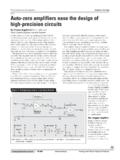
6 As the operating frequency isincreased, the output capacitance(Coss), reverse capacitance (Crss) andan increased saturation voltage low-ers the optimum load line to achievesatisfactory a decade of bandwidth, theoptimum impedance can drop by afactor of two. That is to say that if thelow frequency load line is 6 ohms, theupper operating frequency couldrequire an impedance of 3 ohms withsome amount of inductive or capaci-tive reactance. Figure 1 shows realvalue of Zoutdropping from 11 ohmsat low frequencies to 2 ohms at highfrequency for the transistor has been considerableexperimental and developmentalwork published on the attributes ofcoaxial transformers to achieveextremely wide bandwidths. Thispaper will explore how to combinethe Coaxial transformer with lumpedcomponents to achieve optimal powermatching in a MOSFET power ampli-fier over more than a decade of simulated load pullingwill be utilized to extract the firstorder magnitude of load line match-ing.
7 This impedance information isonly the starting point, since it willbe extracted by a narrow band tech-nique. Broadband extraction is anarea that will be explored in thefuture as the results will take intoaccount more realistic harmonic load-ing and allow more accurate broad-band Design implementation. In thecase of Polyfet transistors, Zin/Zoutdata can be found for each transistorin its respective data the approximate load linehas been determined, let us reviewthe Coaxial transformer matchingtechniques and explore the use ofphysical length, cable impedance,and lumped components in additionto ferrite loading to achieve all the Coaxial transformerdesigns, one of the most practical forwideband impedance matching is the4:1 Design with a balun transformerto achieve optimum balance.
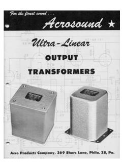
8 Thestandard accepted equation for trans-formation is that the Z0of the cableshould be the square root of the prod-uct of the input and outputimpedances. For example, if the inputimpedance is ohms and the out-put impedance is 50 ohms, then thesquare root of 50 = 25. A 25-ohm impedance cable would give theoptimum results across a wide oper-ating 3 shows a uniformimpedance transformation ratio offour across the frequency band. Itshould be noted for the purpose ofload line Design , impedance is mea-sured drain to drain. This allows sin-gle ended impedance divide the impedance data bytwo to obtain individual device loadimpedance. At 30 MHz the ratio fallsoff due to reactive shunt losses,which could be compensated withFigure 1 Zinand Zout vs.
9 2 Conventional 4:1 transformer with Frequency ElectronicsHigh Frequency DesignBROADBAND Design ferrite loading. The object is todesign a load line that lowers thereal resistance as the requires somerethinking as to how one mightexploit the benefits of transmissionline matching in conjunction withtechniques mentioned above toachieve a satisfactory load line overa decade of Novel ApproachThe following is a presentation ofhow to embed a lumped matchingnetwork into a transmission match-ing network to achieve a suitablebroad band power match. A conven-tional Design allows the coaxialtransformer to transform theimpedance to obtain a match the lowend of the band, then add additionallowpass matching sections to lowerthe impedance at the upper bandedge.
10 Although this technique per-forms satisfactorily, a microstripimplementation would occupy consid-erable novel approach to this problem,shown in Figure 4, is to use the effec-tive inductance of the Coaxial trans-mission lines as the inductive compo-nent in a pi matching network. Onlysmall chip capacitors will be neededto complete the transformation at theupper band edge. By a selection of thetransmission line impedance andelectrical length, a load line may becreated that will essentially providethe basic transformation ratios at thelower band edge. As the operatingfrequency is increased the combina-tion of the transmission line effectiveinductance and the shunt capaci-tance will lower the load line to effec-tively match the device at the upperband edge.