Transcription of BRUSHLESS DC MOTOR & SPEED CONTROL FHD …
1 BRUSHLESS . DC MOTOR . & SPEED CONTROL . DRIVERS. FHD Series dc24v (20, 40W) DC48V (60W). Distinguishing Features 1. Motors are designed small and high performance We recently released a special magnetic circuit design MOTOR . This MOTOR design is smaller and has a higher performance than conventional FED, FYD series motors. Flange size of this series is 61mm sq. ( in sq.). However flange size of 40W & 60W types are 80mm sq. ( in sq.). 2. Compact design Driver "Palm Mini R" Type is the smallest. (20W, 40W only). "Palm Mini PLUS" Type is small. (20W, 40W only). "J - Book" Type is (60W only). High power type is a circuit-board and superconducting type. (20W, 40W). 3. Wide Ranged SPEED CONTROL (60W only).
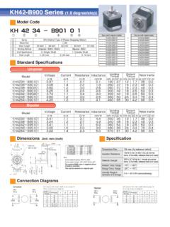
2 Wide range (200r/min-2500r/min 60W:65r/min-2500r/min), stepless SPEED CONTROL . Very steady characteristics (Feed back CONTROL employed). 4. SPEED pulse output SPEED pulse output can be used for SPEED monitoring, simplified position "Palm Mini R" Type: 42 pulse/revolution "Palm Mini PLUS" Type: 42 pulse/revolution "J - Book" Type: 42 pulse/revolution "High power simple" Type: 7 pulse/revolution output is available for SPEED monitoring and simplified position CONTROL are possible. 5. Direction of rotation signal output Direction of rotation can be monitored by this signal. 6. Alarming At an over-load condition, the MOTOR stops and an alarm signal is output. Model Code qSeries name tMotor output shaft type Model on set FHD 6 P 20 PF - D3 wMotor flange dimensions S : Plain shaft 6 : 61 61mm ( in.)
3 PF: Pinion shaft q w e r t y eDriver type PE : Pinion shaft P: Palm mini PLUS type yPower supply voltage J : J - Book type D3: dc24v . rMotor output D5: DC48V. 20: 20W. 40: 40W. 60: 60W. FH 6 PF 20 H - D3 qSeries name rMotor output Model on MOTOR wMotor flange dimensions 20: 20W. 6: 61 61mm ( in.) 40: 40W. q w e r t y eMotor output shaft type tAdapting Driver type S: Plain shaft H: High power simple type driver PF: Pinion shaft R: Palm mini R type driver PE: yPower supply voltage D3: dc24v . Model on driver FHD 6 20 H D3 qSeries name rDriver type wAdapting MOTOR flange dimensions H: High power simple type driver 6: 61 61mm ( in.) R: Palm mini R type driver q w e r t eMotor output (Holding torque can be 20: 20W generated).
4 40: 40W tPower supply voltage D3: dc24v . 1. Palm mini PLUS type J-Book type Specification Plain shaft type FHD6P20S-D3 FHD6P40S-D3 FHD6J60S-D5. Model on set Pinion shaft type FHD6P20PF-D3 FHD6P40PE-D3 FHD6J60PE-D5. Rated voltage V (DC) 24 24 48. Rated output W 20 40 60. SPEED CONTROL range r/min 200~2500 200~2500 65~2500. mN m 98 200 290. Rated torque oz in 14 28 42. MAX. instantaneous mN m 150 (2000r/min MAX.) 290 (500r/min MAX.) 440 (1500r/min MAX.). torque (in 5sec.) oz in 21 (2000r/min MAX.) 42 (500r/min MAX.) 62 (1500r/min MAX.). Rated SPEED r/min 2000 2000 2000. qSpeed setting by external SPEED setter (Sold separately: model code Q-R10KB). SPEED setting method wSpeed setting by external voltage supply 0~10V.
5 SPEED setting (r/min)/V 300 5%. Against load 1% 0~rated torque at rated voltage and SPEED SPEED variation Against voltage 1% Rated voltage 10% at rated SPEED , no load Against temperature 3% 20 20 C at rated voltage and SPEED , no load RUN, BRAKE, F/R IN, ALARM RST (Only 60W). Input H: Open collector L: GND (0~ ). Input and output signal ALARM, SPEED OUT (PULSE OUTPUT), F/R OUT. Output Open collector output DC30V MAX. 10mA MAX. SPEED pulse Pulse/Revolution 42 42 42. Rated (Ave.) MAX. MAX. MAX. Current A. MAX. (Peak) 9 MAX. 10 MAX. 10 MAX. Over load protection When an exceeding torque than rated is applied to MOTOR for more than about 5 sec., Stop MOTOR and outputs "L" from "ALARM" (20W, 40W) or "ALARM OUT" (60W).
6 To release alarm : Protection functions Palm Mini PLUS type: Disconnect power supply for more than 1min J-Book type: Input "L" to "ALARM RST" for more than 1sec. Do not measure/ judge by this operation whether the MOTOR is overloaded or not. Operation temperature: 0~40 C (no condensation) continuous duty. The MOTOR flange surface temp. must be 80 C MAX. (Ambient temperature 40 C. without heat sink). Others MOTOR dielectric strength: Withstand for 1min. under AC500V 50Hz (Between case and coil). MOTOR insulation resistance: 10M MIN. (20W, 40W) 100M MIN. (60W) (Between case and coil by DC500V tester). SPEED (r/min) Applicable MAX. Torque for gearheads Gear ratio 6H EBN 8F EBN. at 200r/min at 2000r/min mN m oz in mN m oz in mN m oz in 5 40 400 390 56 780 110 1200 170.
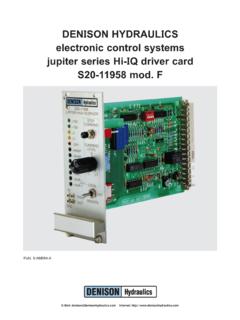
7 10 20 200 780 110 1600 220 2400 330. 25( ) 8 80 1700 250 3600 510 5500 780. 50( ) 4 40 3500 500 7000 1000 10600 1500. : rotation of gear head output shaft becomes reverse direction of motors. In case of 8F EBN value in ( ) should be used as gear ratio. 6. Torque SPEED /Current (TYP.) Characteristics MOTOR outlines (Plain shaft type). FHD6P20S(PF)-D3 Unit: mm (inch). (r/mim) [A]. 3000 3. n in min min /mi Input Current (Ave.). r/m r/ r/ r 0 00 00 00. 50 10 15 20. Continuation operation area 2000 2. SPEED Short time rating area 1000 1. 200. 0 50 100 150 200 mN m 0 50 100 150 200 mN m ( ) (14) (21) (28) (oz in) ( ) (14) (21) (28) (oz in). Torque Torque FHD6P40S(PE)-D3. Weight 10 00 r in (r/mim) [A].
8 R/m in m 00 /m Model L D:dia in 3000 3 15 0 r/. Kg (lb). 0. Input Current (Ave.). 20. in r/m q FHD6P20S-D3 46 ( ) 8 ( ) Continuation operation area 2000 2. 0. w FHD6P40S-D3 60 ( ) 8 ( ) SPEED 50. e FHD6J60S-D5 60 ( ) 10 ( ) Short time rating 1000 1. area 200. 0 100 200 300 400 mN m 0 100 200 300 400 mN m (14) (28) (42) (56) (oz in) (14) (28) (42) (56) (oz in) Connection guide Torque Torque 20 / 40W 60W. Symbol q w Lead wire e Lead wire Remark FHD6J60S(PE)-D5 PIN # color PIN # color (r/mim) [A] Coil U 1 Brown 3 Brown 3000 3. in Coil V 2 Red 4 Red r/m r/m 15 min Input Current (Ave.). MOTOR connector 00. Coil W 3 Orange 8 Orange r/. in 00. 2000 2. Continuation operation area 20. 4.
9 0. SPEED 0. 10. in r/m Short time rating area HW 5 Green 7 Green Open collector 0. 50. 1000 1. HV 6 Blue 6 Blue Open collector 65. HU 7 Purple 5 Purple Open collector 0 200 400 600 800 mN m 0 200 400 600 800 mN m GND 8 Gray 1 Gray (28) (56) (85) (oz in) (28) (56) (85) (oz in). Torque Torque 12V 9 White 2 White MOTOR (Pinion shaft type) + Gear head outlines FHD6P20PF-D3+6H EBN. Unit: mm (inch). FHD6P40PE-D3+8F EBN. FHD6J60PE-D5+8F EBN. 7. Input & output terminals and wiring diagram FHD6P20S(PF)-D3. FHD6P40S(PE)-D3. Input or Driver Item Pin No. Symbol Function Standard Condition Controller etc. Output I O 5V MOTOR MOTOR 10K 1. RUN. Power 1 VM Input Power supply positive for driver 10.
10 5V. dc24v 10%. supply 2 Power supply GND for driver BRAKE. 9. 10K . 5V 9. 1 SPEED OUT Output 42 Pulse/Revolution *3 *1 H: Open collector 5V. F/R IN. 8. 10K . H: CCW L: CW DC30V MAX. R1 R1 R1 ALARM. 7. 2 F/R OUT Output L: 0~ 10mA MAX. (Viewed from MOTOR output shaft side) *7 C1. GND. 6. Power supply positive GND. 3 VR Output 5. for external SPEED setter External SPEED setter VS. 10K 4. 4 VS Input SPEED setting signal positive Optional part 12V About 0~10V VR. 3. 80K . 5 GND SPEED setting signal GND *7. 5V . R1 R1 R1 F/R OUT. 2. 6 GND GND for I/O Signal C1 5V. R1 R2 R2 SPEED OUT. I/O ALARM H: Normal operation 1. 7 Output Same as *1 C1. OUT L: Alarm output Power supply H: CCW L: CW *2 H: Open 8 F/R IN Input 2.