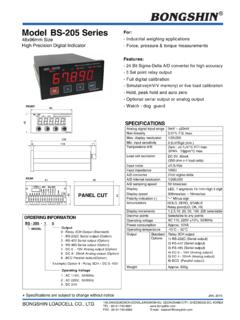
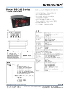
Transcription of BS-205[영문] 매뉴얼 Ver4 - BONGSHIN LOADCELL …
1 1. CONTENTS. Introductions .. 2. The Features of BS-205 .. 3. Technical Specification .. 4. Dimensions .. 6. Front Panel .. 7. Rear Panel .. 9. Parameter .. 16. ZERO Calibration .. 21. Actual Load Calibration .. 22. Equivalent Calibration .. 24. Comparator Data .. 26. Hold Function .. 34. Key Lock .. 36. Option .. 37. Error Message and Trouble Shooting .. 47. 2. Introduction 1. Introduction Thank you for purchasing BS-205 High precision digital indicator. Check for any breakdown during transit and discrepancy of the specification. Always keep this manual at hand. The BS-205 Series are configured as follows : Check that there is no discrepancy between the model and its specifications you have chosen when ordering and the model and its specifications under your hand. In order to obtain the highest performance of your BS-205, thoroughly read this manual before use.
2 2. Precautions Place the indicator on a flat and stable surface. Applying voltage and current exceeding the maximum permissible value results in the breakdown of the meter. Do not severely press because the light pressing of keys can incite the operation. Do not subject the scale to sudden temperature changes. Operating temperature : -10 ~+50 . Keep the scale away from strong EMI noises may cause incorrect weight readings. Keep the main body from rain and keep in dry area. Do not use inflammable materials in cleaning. The contents of this manual are subject to change without notice for further improvement. 3. The Features of BS-205. 1. Features Appropriate for weight and measurement system. 24 bit Sigma-Delta A/D converter for high accuracy. Simple full digital calibration. Simulative (mV/V memory) or live load calibration.
3 Watchdog circuitry (system restoration). Weight Back-up (power on actual weight). 2. Main Function Various specification of weight conversion speed. (Digital Filter Function). 3 Set point relay output. Hold, peak hold and auto zero. Option serial output or analog output. User can set the max. weight which users want to and division at one's disposal. 4. Technical Specification 1. Analog Input & A/D Conversion Analog signal input range 0 mV ~ 20 mV. Non-linearity max. Max. Display resolution 1/20,000. Min. Input sensitivity V/Digit (min.). Zero : V/ RTI max. Temperature drift Span : 10ppm/ max. Load cell excitation DC 5V 5%, 60 . Voltage up to 4 x 350 ohm load cells Input Noise V or less Input Impedance 10 (Min.). A/D converter 24bit Sigma-Delta system A/D internal resolution Approximately 200,000 counts A/D sampling speed 50 times/sec 2.
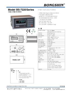
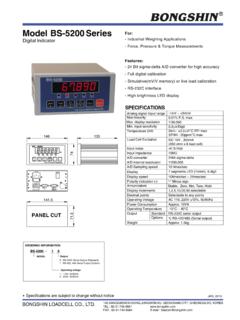
4 Digital Part 7 Segment LED, Display 5-Digits, (Height). Display below zero - minus signal Display speed 50 times/sec ~ 1 times/sec Hold, Zero, Stable, Additional symbols Relay point(LO, OK, HI). Min. Division 1, 2, 5, 10, 20, 50, 100, 200 selectable Decimal Point 0, , , 5. 3. Technical AC adapter AC 110, 220V 10%, 50/60Hz Power consumption 10 VA. Data Memory 10 year Operating temperature -10 ~+50 . Humidity 85% Rh Max. Overall dimensions 96(W) x 48(H) x 136(D). Weight 530 g 4. Option Standard Relay 3CH Output Option 1 Serial Interface RS-232C. Option 2 Serial Interface RS-422. Option 3 Serial Interface RS-485. Option 4 Analog Output DC 0~10V. Option 5 Analog Output DC 4~20mA. Option 6 BCD Parallel Output Example) Option 4 : Relay 3CH + DC 0 ~ 10V. 6. Dimensions 96. BS - 205 High Precision DIGITAL INDICATOR.
5 LO OK HI HOLD ZERO STABLE. 48. M. BONGSHIN . 136. 6 119 11. 91 92. 43. 44. Dimensions for cutting panel To mount the BS-205 to the panel, remove its fittings and insert it through the hole in the front of the panel. From the back of the panel, fix the product to the panel with the fittings. 7. Front Panel BS - 205 High Precision DIGITAL INDICATOR. LO OK HI HOLD ZERO STABLE. M 1 2 3 4. BONGSHIN . 1. Display Lamp ( ). LO (L1) lamp : It will lamp when 1step control works. Indicates the result of judgment and turns on if the measured value < LO judgment value. OK (L2) lamp : It will lamp when 2step control works. Indicates the result of judgment and turns on if LO judgment value the measured value . HI judgment value. HI (L3) lamp : It will lamp when 3step control works. Indicates the result of judgment and turns on if the measured value > HI judgment value.
6 HOLD lamp : Lamp is on when moving object is weighed. Turns on if peak hold/ instant hold is on. ZERO lamp : ON when the current weight is 0 kg. Turns on if digital zero is on. STABLE lamp : ON when the weight is stable. 8. 2. Keyboard 1) Pressing the increments and mode keys together changes M. to the parameter setting mode. 2) Returns to the measurement mode.(ESC). 1. 3) Selects the item to be set. 1) Holding down the increment key for about two second moves to the peak hold & instant mode. 2 2) Changes the value or content of a selected digit. (Increments the value). 1) Holding down the increment key for about one second moves to the peak hold & instant clear mode. 3. 2) Changes the digit to be set. 1) Store current condition and exit. 4. M 1. +. 2. = Parameter setting mode M + = Relay setting mode 1 3.
7 4. + = Digital zero function 2. 4. + = Key LOCK or Key LOCK clear mode 3. 9. Rear Panel OPTION INPUT RELAY OUTPUT. 1 2 3 4. HI (L3). OK (L2). LO (L1). COM1. COM2. HOLD. ZERO. POWER. SHIELD. S+. E+. S- E- (GROUND) : It is a grounding terminal. Ground it to prevent an electric shock and a trouble of static electricity. POWER(AC IN) : Use a stable power supply AC110/220V 10%, 50/60Hz - Set up voltage AC220V. Connect power supply to terminals (L) and (N). Pin No.. Power terminal without polarity for both 13 POWER. DC and AC. Power terminal without polarity for both 14 POWER. DC and AC. 15 Frame Ground 10. LOAD CELL : Please connect the indicator connector with the wire of load cell according to the color. Pin no. Signal name Contents 1 SIG- (Blue) Load cell output (-). 2 SIG+ (Green) Load cell output (+).
8 3 EXC- (White) Load cell Input Voltage (-). 4 EXC+ (Red) Load cell Input Voltage (+). 5 SHIELD Shield The wire color of load cell according to a manufactures. 1 2 3 4 5. Maker SIG- SIG+ EXC- EXC+ SHIELD. BONGSHIN BLUE GREEN WHITE RED SHIELD. CAS, TMI, AND BLUE GREEN WHITE RED SHIELD. BLH RED WHITE BLACK GREEN YELLOW. INTERFACE WHITE GREEN BLACK RED SHIELD. KYOWA WHITE GREEN BLACK RED SHIELD. WHITE GREEN BLACK RED SHIELD. SHOWA BLACK WHITE BLUE RED SHIELD. SHINKOH WHITE GREEN BLACK RED SHIELD. TML GREEN WHITE BLACK RED SHIELD. TFAC BLACK WHITE BLUE RED YELLOW. HUNTLEIGH WHITE RED BLACK GREEN SHIELD. Because wire color may be different according to a manufacture and load cell models. Please refer for the data sheet of load cell. Cautions 1. When connecting a six-wire type strain gage sensor, short- circuit (EXC+ and SEN+)(EXC- and SEN-), respectively.
9 Cautions 2. Applied voltages to the strain gage sensor are 10. When any sensor rated below the applied voltage is connected, it may generate heat or be damaged 11. IN-PUT : COM1, ZERO, HOLD. This key is to control a equipment from the outside . Please connect between COM terminal and each input terminal . Because the power of input terminal was connected with 12V voltage From the inside. * An electric current is about 10mA. * Please make the minimum time to input a data with over 50msec. Pin No. Name Description 6 COM1 Common for all external control terminals. Control for digital zero function. Enabled when 7 ZERO. short-circuited or at the same potential as COM. Control for hold function. Enabled when short- 8 HOLD. circuited or at the same potential as COM. 12. RELAY OUTPUT : COM2, HI(L3), OK(L2), LO(L1).
10 Connect between COM terminal and OUTPUT terminal With the earth of no electric power. Please use the output data For a signal only, don't use it for working. Max earth capacity : AC250V / Pin No. Name Description 9 COM2 Common terminal for relay output 10 HI (L3) HI (L3) output terminal (a, b contact). 11 OK (L2) OK (L2) output terminal (a, b contact). 12 LO (L1) LO (L1) output terminal (a, b contact). 13. OPTION : Analog output (0~10V, 4~20mA) & Serial communication (RS-232C, RS-422/485) option. Analog output (0~10V, 4~20mA) option Pin No. Name Description 1 V-OUT Voltage output terminal (0 to 10V). 2 COM Common terminal for analog output. 3 COM Common terminal for analog output. 4 A-OUT Current output terminal (4 to 20mA). Serial output (RS-232C) option Pin No. Name Description 1 RX RS-232C reception 2 TX RS-232C transmission 3 SG Common terminal for communications 4 NC Do not connect this terminal Serial output (RS-422) option Pin No.