Transcription of BSIM4.3.0 MOSFET Model
1 MOSFET Model - User s ManualXuemei (Jane) Xi, Mohan Dunga, Jin He, Weidong Liu, Kanyu M. Cao, Xiaodong Jin, Jeff J. Ou, Mansun Chan, Ali M. Niknejad, Chenming HuProject Director: Professor Chenming HuProfessor Ali Niknejad Department of Electrical Engineering and Computer SciencesUniversity of California, Berkeley, CA 94720 Copyright 2003 The Regents of the University of CaliforniaAll Rights Developers: Professor Chenming Hu (project director), UC Berkeley Professor Ali M. Niknejad(project director), UC Berkeley Dr. Xuemei (Jane) Xi , UC Berkeley Dr. Jin He , UC Berkeley Mr. Mohan Dunga, UC BerkeleyDevelopers of BSIM4 Previous Versions: Dr. Weidong Liu, Synopsys Dr. Xiaodong Jin, Marvell Dr. Kanyu (Mark) Cao, UC Berkeley Dr. Jeff J. Ou, Intel Dr. Xuemei (Jane) Xi, UC Berkeley Professor Chenming Hu, UC BerkeleyWeb Sites:BSIM4 web site with BSIM source code and documents: ~ Model Council: ~CMCT echnical Support: Dr.
2 Xuemei (Jane) Xi: development of benefited from the input of many BSIM users, especially the Compact Model Council (CMC) member developers would like to thank Keith Green, Tom Vrotsos, BrittBrooks and Doug Weiser at TI, Joe Watts and Richard Q Williams at IBM,Yu-Tai Chia, Ke-Wei Su, Chung-Kai Chung, Y-M Sheu and Jaw-KangHer at TSMC, Rainer Thoma, Ivan To, Young-Bog Park and ColinMcAndrew at Motorola, Ping Chen, Jushan Xie, and Zhihong Liu atCelestry, Paul Humphries, Geoffrey J. Coram and Andre Martinez atAnalog Devices, Andre Juge and Gilles Gouget at STmicroelectronics,Mishel Matloubian at Mindspeed, Judy An at AMD, Bernd Lemaitre,Laurens Weiss and Peter Klein at Infinion, Ping-Chin Yeh and DickDowell at HP, Shiuh-Wuu Lee, Wei-Kai Shih, Paul Packan, Sivakumar PMudanai and Rafael Rio at Intel, Xiaodong Jin at Marvell, Weidong Liu atSynopsys, Marek Mierzwinski at Tiburon-DA, Jean-Paul MALZAC atSilvaco, Pei Yao and John Ahearn at Cadence, Mohamed Selim andAhmed Ramadan at Mentor Graphics, Peter Lee at Hitachi, ToshiyukiSaito and Shigetaka Kumashiro at NEC, Richard Taylor at NSC, for theirvaluable assistance in identifying the desirable modifications and testing ofthe new acknowledgment goes to Dr.
3 Keith Green, Chairman of theTechnical Issues Subcommittee of CMC; Britt Brooks, chair of CMC, Watts, Secretary of CMC, and Dr. Ke-Wei Su for their guidance andtechnical BSIM project is partially supported by SRC, and Manual Copyright 2001 UC Berkeley 1 Table of ContentsChapter 1:Effective Oxide Thickness, Channel Length and Channel Width Gate dielectric Poly-Silicon Gate Effective Channel Length and Width1-5 Chapter 2:Threshold Voltage Model Long-Channel Model With Uniform Non-Uniform Vertical Non-Uniform Lateral Doping: Pocket (Halo) Short-Channel and DIBL Narrow-Width Effect2-9 Chapter 3:Channel Charge and Subthreshold Swing Models Channel Charge Subthreshold Swing n3-5 Chapter 4:Gate Direct Tunneling Current Model Model Voltage Across Oxide Equations for Tunneling Currents4-3 Chapter 5:Drain Current Model Bulk Charge Mobility and Bias-Dependent Source/Drain Resistance Drain Current for Triode Velocity Voltage Output Conductance Channel Current Manual Copyright 2001 UC Berkeley 2 New Current Saturation Mechanisms: Velocity Overshoot and Source End Velocity Limit Model 5-17 Chapter 6:Body Current Models Iii IGIDL Model6-2 Chapter 7:Capacitance Model General for Intrinsic Capacitance Capacitance Model (CTM) Capacitance Model Capacitance Models7-19 Chapter 8:High-Speed/RF Modelsm Non-Quasi-Static (NQS) Electrode Electrode and Intrinsic-Input Resistance (IIR) Resistance Network8-8 Chapter 9:Noise Modeling Flicker Noise Thermal Noise Sources Modeled9-7 Chapter 10:Asymmetric MOS Junction Diode Models Diode IV Diode CV Model10-6 Chapter 11.
4 Layout-Dependent Parasitics Model Geometry Formulation and Options11-3 Chapter 12:Temperature Dependence Model Dependence of Threshold Manual Copyright 2001 UC Berkeley 3 Dependence of Dependence of Saturation Dependence of LDD Dependence of Junction Diode Dependence of Junction Diode Dependences of Eg and ni12-8 Chapter 13:Stress effect Model Stress effect Model Effective SA and SB for irregular LOD13-2 Chapter 14:Parameter Extraction Methodology Extraction Procedure14-3 Appendix A:Complete Parameter List Model Process Model for Asymmetric and Bias-Dependent Rds Ionization Current Model Drain Leakage Model dielectric Tunneling Current Model and Capacitance Model Model and Thermal Noise Model Parasitics Model Source/Drain Junction Diode Model Dependence and dL Parameters for Model Notes Manual Copyright 2001 UC Berkeley 4 Appendix B:Core Parameter List for General Parameter ExtractionB-1 Appendix Manual Copyright 2003 UC Berkeley1-1 Chapter 1: Effective Oxide Thickness, Channel Length and Channel WidthBSIM4, as the extension of BSIM3 Model , addresses the MOSFET physicaleffects into sub-100nm regime.
5 The continuous scaling of minimum feature sizebrought challenges to compact modeling in two ways: One is that to push thebarriers in making transistors with shorter gate length, advanced processtechnologies are used such as non-uniform substrate doping. The second is itsopportunities to RF applications. To meet these challenges, BSIM4 has the following major improvements andadditions over BSIM3v3: (1) an accurate new Model of the intrinsic inputresistance for both RF, high-frequency analog and high-speed digital applications;(2) flexible substrate resistance network for RF modeling; (3) a new accuratechannel thermal noise Model and a noise partition Model for the induced gatenoise; (4) a non-quasi-static (NQS) Model that is consistent with the Rg-based RFmodel and a consistent AC Model that accounts for the NQS effect in bothtransconductances and capacitances.
6 (5) an accurate gate direct tunneling modelfor multiple layer gate dielectrics; (6) a comprehensive and versatile geometry-dependent parasitics Model for various source/drain connections and multi-fingerdevices; (7) improved Model for steep vertical retrograde doping profiles; (8)better Model for pocket-implanted devices in Vth, bulk charge effect Model , andRout; (9) asymmetrical and bias-dependent source/drain resistance, either internalor external to the intrinsic MOSFET at the user's discretion; (10) acceptance ofeither the electrical or physical gate oxide thickness as the Model input at the user'sGate dielectric Model1-2 Manual Copyright 2003 UC Berkeleychoice in a physically accurate maner; (11) the quantum mechanical charge-layer-thickness Model for both IV and CV; (12) a more accurate mobility Model forpredictive modeling; (13) a gate-induced drain/source leakage (GIDL/GISL)current Model , available in BSIM for the first time; (14) an improved unifiedflicker (1/f) noise Model , which is smooth over all bias regions and considers thebulk charge effect ; (15) different diode IV and CV charatistics for source and drainjunctions; (16) junction diode breakdown with or without current limiting; (17) dielectric constant of the gate dielectric as a Model parameter; (18) A new scalablestress effect Model for process induced stress effect ; device performancebecoming thus a function of the active area geometry and the location of thedevice in the active area.
7 (19) A unified current-saturation Model that includes allmechanisms of current saturation- velocity saturation, velocity overshoot andsource end velocity limit; (20) A new temperature Model format that allowsconvenient prediction of temperature effects on saturation velocity, mobility, andS/D dielectric ModelAs the gate oxide thickness is vigorously scaled down, the finite charge-layerthickness can not be ignored [1]. BSIM4 models this effect in both IV and CV. Forthis purpose, BSM4 accepts two of the following three as the Model inputs: theelectrical gate oxide thickness TOXE1, the physical gate oxide thickness TOXP,and their difference DTOX = TOXE - TOXP. Based on these parameters, the effectof effective gate oxide capacitance Coxeff on IV and CV is modeled [2].1. Capital and italic alphanumericals in this manual are Model dielectric Manual Copyright 2003 UC Berkeley 1-3 High-k gate dielectric can be modeled as SiO2 (relative permittivity: ) with anequivalent SiO2 thickness.
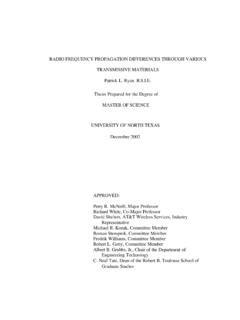
8 For example, 3nm gate dielectric with a dielectricconstant of would have an equivalent oxide thickness of also allows the user to specify a gate dielectric constant (EPSROX)different from (SiO2) as an alternative approach to modeling high-k 1-1 illustrates the algorithm and options for specifying the gate dielectricthickness and calculation of the gate dielectric capacitance for BSIM4 1-1. Algorithm for BSIM4 gate dielectric given?TOXE and TOXP both given?NoYesTOXP given?NoYesYesNoTOXE TOXETOXP TOXPTOXE TOXETOXP TOXE - DTOXTOXE TOXP + DTOXTOXP TOXPD efault case TOXEEPSROXCoxe0 =, Coxe is used to calculate Vth, subthreshold swing, Vgsteff, Abulk,mobiliy, Vdsat, K1ox, K2ox, capMod = 0 and 1, etc TOXPEPSROXCoxp0 =, Coxp is used to calculate Coxeff for drain current and capMod =2 through the charge-layer thickness Model :() ++ = TOXPVFBVTHVX sgsteffDC If DTOX is not given, its default value will be Gate Manual Copyright 2003 UC Berkeley 1-4 Gate DepletionWhen a gate voltage is applied to the poly-silicon gate, NMOS with n+ poly-silicon gate, a thin depletion layer will be formed at the interface between the poly-silicon and the gate oxide.
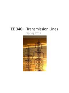
9 Although this depletion layer is very thin due to the highdoping concentration of the poly-silicon gate, its effect cannot be ignored since thegate oxide thickness is 1-2 shows an NMOSFET with a depletion region in the n+ poly-silicongate. The doping concentration in the n+ poly-silicon gate is NGATE and thedoping concentration in the substrate is NSUB. The depletion width in the polygate is Xp. The depletion width in the substrate is Xd. The positive charge near theinterface of the poly-silicon gate and the gate oxide is distributed over a finitedepletion region with thickness Xp. In the presence of the depletion region, thevoltage drop across the gate oxide and the substrate will be reduced, because partof the gate voltage will be dropped across the depletion region in the gate.
10 Thatmeans the effective gate voltage will be Gate Manual Copyright 2003 UC Berkeley 1-5 Figure 1-2. Charge distribution in a MOSFET with the poly gate depletion effect . The device is in the strong inversion effective gate voltage can be calculated in the following manner. Assume thedoping concentration in the poly gate is uniform. The voltage drop in the poly gateVpoly can be calculated as( )where Epoly is the maximum electrical field in the poly gate. The boundarycondition at the interface of poly gate and the gate oxide isNGATE sipolypolypolypolyXqNGATEEXV ==Poly-Silicon Gate Manual Copyright 2003 UC Berkeley 1-6 ( )where Eox is the electric field in the gate oxide. The gate voltage satisfies( )where Vox is the voltage drop across the gate oxide and satisfies Vox = ( ) and ( ), we can obtain( )where( )By solving ( ), we get the effective gate voltage Vgse which is equal to( )polysipolysioxVNGATEqEEEPSROX == 2oxpolysFBgsVVVV+= ()02= polypolysFBgsVVVVa222 TOXENGATEqEPSROXasi = () + + +=1212222 TOXENGATEqVFBVEPSROXEPSROXTOXENGATEqVFBV sisgssisgse Effective Channel Length and Manual Copyright 2003 UC Berkeley 1-7 Channel Length and WidthThe effective channel length and width used in the drain current Model are givenbelow where XL and XW are parameters to account the channel length/widthoffset due to mask/etch effect ( )( )( )The difference between ( ) and ( ) is that the former includes biasdependencies.