Transcription of BUILDING AIR INTAKE AND EXHAUST DESIGN - ASHRAE
1 46 BUILDING AIR INTAKE AND EXHAUST DESIGNE xhaust Stack and Air INTAKE DESIGN Method for Estimating Stack Dilution or Concentration air enters a BUILDING through its air INTAKE to provideO ventilation air to BUILDING occupants. Likewise, BUILDING ex-haust systems remove air from a BUILDING and expel the contaminantsto the atmosphere. If the INTAKE or EXHAUST system is not well de-signed, contaminants from nearby outdoor sources ( , vehicle ex-haust, emergency generators, EXHAUST stacks on nearby buildings) orfrom the BUILDING itself ( , laboratory fume hood EXHAUST , plumb-ing vents) can enter the BUILDING before dilution. Poorly diluted con-taminants may cause odors, health impacts, and reduced indoor airquality. This chapter discusses proper DESIGN of EXHAUST stacks andplacement of air intakes to avoid adverse air quality 24 of the 2017 ASHRAE Handbook Fundamentals de-scribes wind and airflow patterns around buildings in greater information can also be found in Chapters 9, 18, 33, 34, and35 of this volume, Chapters 11 and 12 of the 2017 ASHRAE Hand-book Fundamentals, and Chapters 29, 30, and 35 of the 2016 ASHRAE Handbook HVAC Systems and STACK AND AIR INTAKE DESIGN STRATEGIESS tack DESIGN StrategiesThe dilution a stack EXHAUST can provide is limited by the disper-sion capability of the atmosphere.
2 Before discharging out the stack, EXHAUST contamination can be reduced by filters, collectors, andscrubbers to maintain acceptable air quality. The goal of stack designis to specify the minimum flow of the EXHAUST system, exhaustvelocity, and stack height that ensures acceptable air quality at alllocations of concern. This also reduces the EXHAUST system s EXHAUST systems that combine airflows from many ex-haust sources should always be used where safe and practical. Bycombining several EXHAUST streams, central systems can dilute con-taminants in the EXHAUST airstream more efficiently. The combinedflow can generate an EXHAUST plume that rises a greater distanceabove the emitting BUILDING . If necessary for air quality reasons, ad-ditional air volume can be added to the EXHAUST near the exit with amakeup air unit to increase initial dilution and EXHAUST plume added air volume does not need heating or cooling, and the ad-ditional energy cost is lower than increasing stack exit velocity.
3 Asmall increase in stack height may also achieve the same benefitwithout an added energy some cases, separate EXHAUST systems are mandatory. Thenature of the contaminants to be combined, recommended industrialhygiene practice, and applicable safety codes need to be EXHAUST stacks could be grouped in close proximity to oneanother to take advantage of the larger plume rise of the resultingcombined jet. Also, a single stack location for a central exhaustsystem or a tight cluster of stacks provides more options for locatingbuilding air intakes on the BUILDING facade or roof. Petersen andReifschneider (2008) provide guidelines for optimal arrangementsof ganged stacks. In general, for a tight cluster to be considered as asingle stack ( , to add stack momentums together) in dilution cal-culations, the stacks must be uncapped and nearly be touching themiddle stack of the shown in Figure 1, stack height hs is measured from the rooflevel on which the EXHAUST stack is located to the top of the and Winkel (1982) demonstrated that stacks terminatingbelow the level of adjacent walls and architectural enclosures fre-quently do not effectively reduce roof-level EXHAUST take full advantage of their height, stacks should be located on thehighest roof of a screens used to mask rooftop equipment adverselyaffect EXHAUST dilution, depending on porosity, relative height, anddistance from the stack.
4 Petersen et al. (1999) found that EXHAUST dis-persion improves with increased screen buildings, structures, and terrain close to the emitting build-ing can adversely affect stack EXHAUST dilution, because the emittingbuilding can be within the recirculation flow zones downwind ofthese nearby flow obstacles (Wilson et al. 1998a). In addition, venti-lation air entering air intakes located on nearby taller buildings can becontaminated by stack EXHAUST from shorter buildings. Wherever pos-sible, facilities emitting toxic or highly odorous contaminants shouldnot be located near taller buildings or at the base of steep shown in Figure 2, stacks should be vertically directed anduncapped. Stack caps that deflect the EXHAUST jet have a detrimentaleffect on EXHAUST plume rise. Small conical stack caps often do notcompletely exclude rain, because rain does not always fall straightdown; periods of heavy rainfall may be accompanied by high windsthat deflect raindrops under the cap and into the stack (Changnon1966).
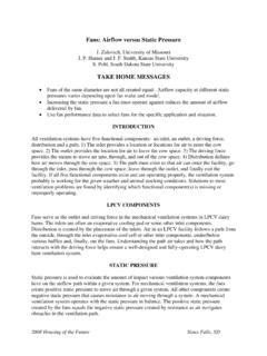
5 A stack EXHAUST velocity Ve of about 2500 fpm prevents con-densed moisture from draining down the stack and keeps rain fromentering the stack. For intermittently operated systems, protectionfrom rain and snow should be provided by stack drains, as shown inFigure 2F to 2J, rather than stack Stack EXHAUST VelocityHigh stack EXHAUST velocity and temperatures increase plumerise, which tends to reduce INTAKE contamination. EXHAUST velocityThe preparation of this chapter is assigned to TC , Ventilation Require-ments and 1 Flow Recirculation Regions and EXHAUST Parameters(Wilson 1982) ASHRAE Handbook HVAC Applications Ve should be maintained above 2000 fpm (even with drains in thestack) to provide adequate plume rise and jet dilution. Velocitiesabove 2000 fpm provide greater plume rise and dilution, but above3000 to 4000 fpm, noise, vibration, and energy costs can become animportant concern. An exit nozzle (Figure 2B) can be used to in-crease EXHAUST velocity and plume rise.
6 Many laboratory fume hoodsystems use variable-volume fans that reduce flow from hoods whenthey are closed. Stack EXHAUST velocity calculations must be based onthe minimum total flow rate from the system, not the exception to these EXHAUST velocity recommendations includewhen corrosive condensate droplets are discharged. In this case, avelocity of 1000 fpm in the stack and a condensate drain are recom-mended to reduce droplet emission. At this low EXHAUST velocity, ataller stack may be needed to counteract downwash caused by lowexit velocity. Another exception is when a detailed dispersion mod-eling analysis is conducted. Such an analysis can determine the min-imum exit velocity needed to maintain acceptable dilution versusstack height. Generally, the taller the stack, the lower the requiredexit velocity and fan energy wake downwash occurs where low-velocity exhausts arepulled downward by negative pressures immediately downwind ofthe stack, as shown in Figure 3.
7 Ve should be at least times thedesign speed UH at roof height in the approach wind to avoid stackwake downwash. A meteorological station DESIGN wind speed Umetthat is exceeded less than 1% of the time can be used as UH. Thisvalue can be obtained from Chapter 14 of the 2017 ASHRAE Hand-book Fundamentals, or estimated by applying Table 2 of Chapter24 of that volume to annual average wind speed. Because wind speedincreases with height, a correction for roof height should be appliedfor buildings significantly higher than 30 ft, using the power law ruledescribed in Equation (4) and Table 1 of Chapter 24 of the 2017 ASHRAE Handbook Stack DESIGN StandardsMinimum heights for chimneys and other flues are discussed inthe International BUILDING Code (ICC 2006). For laboratory fumehood exhausts, American Industrial Hygiene Association (AIHA)Standard recommends a minimum stack height of 10 ft abovethe adjacent roof line, an EXHAUST velocity Ve of 3000 fpm, and astack height extending one stack diameter above any architecturalscreen; National Fire Protection Association (NFPA) Standard 45specifies a minimum stack height of 10 ft to protect rooftop work-ers.
8 Toxic chemical emissions may also be regulated by federal,state, and local air quality SourcesSome contamination sources that need consideration in stack andintake DESIGN include the Stack Exhausts. Boilers, emergency generators, and lab-oratory fume hoods are some sources that can seriously affectbuilding indoor air quality because of toxic air pollutants. Thesesources, especially diesel-fueled emergency generators, can alsoproduce strong odors that may require administrative measures,such as generator testing during low BUILDING occupancy or tempo-rarily closing the and Truck Traffic. Heavily traveled roads andparking garages emit carbon monoxide, dust, and other trucks and ambulances are common sources of odor com-plaints (Smeaton et al. 1991). Avoid placing intakes near vehicleloading zones. Overhead canopies on vehicle docks do not preventhot vehicle EXHAUST from rising to intakes above the canopy.
9 Whenthe loading zone is in the flow recirculation region downwind fromthe BUILDING , vehicle EXHAUST may spread upwind over large sectionsof the BUILDING surface (Ratcliff et al. 1994). Garbage containersmay also be a source of odors, and garbage trucks may emit dieselexhaust with strong Cooking Hoods. Kitchen EXHAUST can be a source ofodors and cause plugging and corrosion of heat exchangers. Greasehoods have stronger odors than other general kitchen and odor removal equipment beyond that for code require-ments may be needed if air intakes cannot be placed an appropriatedistance Cooling Towers. Outbreaks of Legionnaires dis-ease have been linked to bacteria in cooling tower drift dropletsbeing drawn into the BUILDING through air intakes (Puckorius 1999). ASHRAE Guideline 12 gives advice on cooling tower maintenancefor minimizing the risk of Legionnaires disease, and suggestskeeping cooling towers as far away as possible from intakes, oper-Fig.
10 2 Stack Designs Providing Vertical Discharge and Rain ProtectionFig. 3 Reduction of Effective Stack Height by Stack Wake DownwashBuilding Air INTAKE and EXHAUST windows, and outdoor public areas. No specific minimum sep-aration distance is provided or available. Prevailing wind directionsshould also be considered to minimize risk. Evaporative coolingtowers can have several other effects: water vapor can increase air-conditioning loads, condensing and freezing water vapor can dam-age equipment, and ice can block INTAKE grilles and filters. Chemi-cals added to retard scaling and biological contamination may beemitted from the cooling tower, creating odors or health effects, asdiscussed by Vanderheyden and Schuyler (1994). BUILDING General EXHAUST Air. General indoor air that is ex-hausted normally contains elevated concentrations of carbon diox-ide, dust, copier toner, off-gassing from materials, cleaning agents,and body odors. General EXHAUST air should not be allowed to reenterthe BUILDING without sufficient Water Bodies, Snow, and Leaves.