Transcription of Bulletin 210-60 OCTOBER1994 THERMOSTATIC EXPANSION …
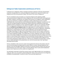
1 Bulletin 210-60 OCTOBER1994 THERMOSTATIC EXPANSION VALVESIDENTlFlCATlONTo completely identify a SPORLAN THERMOSTATIC EXPANSION valve the following informationis required:To completely identify a SPORLAN THERMOSTATIC element the following information is of valve (body style) in tons of refrigeration or port of THERMOSTATIC bulb size if other than letters if any indicate permanent bleed port or Rapid Pressure Balancer con-struction.(All valves except Types A & D) and outlet connection sizes and tubing letters or number if anyFor detailed explanation see Sections 1 thru size (Maximum operating Pressure) if other than tubing size if other than standard (See Section 6)For detailed explanation see Sections 5,6 and Designation,Letter andColor Code Used on -R-11-BlueF -R12 -YellowE -R-13 -BlueT -R-13B1-BlueV -R-22 -GreenG -R-23 -BlueB -R-114 -BlueQ -R124 ~ GreenJ -R-134a -BlueL -R-402A -SandS -R-404A -OrangeD -R-500 -OrangeR -R-502 -PulpleW -R-503 -BlueP -R-507 -TealA -R-717 -WhiteReplaceable THERMOSTATIC Elementsmanufactured after 1991 had the ele-ment number and thermostaticcharge marked on top of the GTYPE DTYPE MTYPE S584182942188958123849543218859 FECBDEFFABCDLock RingDate VALVE -Sporlan THERMOSTATIC EXPANSION valvesare available in three body styles SAE flare, ODF sol-der, or flange.
2 The first letter or letters stamped on thevalve body and shown on the label designates the valvetype. Valve types are listed -Sporlanvalves are available for use withmost popular refrigerants. The letter stamped on the valvebody following the valve type and shown on the label desig-nates the refrigerant . refrigerant designations are as EQUALIZER -The letter E immediatelyfollowing the letter designating the refrigerant is used todenote an external equalizer connection. Physical inspec-tion of the valve will reveal whether or not an externalequalizer connection has been IN TONS of REFRIGERATlON or PORT SIZE -For all current production valves except the Types(E)BF & SBF, the number following the letters indicatesthe valve s nominal capacity rating in tons. For example, avalve marked GF-1 is a Type G valve for refrigerant 12with a one ton nominal capacity rating.
3 A valve markedSVE-5 is an externally equalized Type S valve forRefrigerant 22 with a five ton nominal capacity current production Types (E)BF and SBF valves, and Type(E)BS valves, manufactured prior to 1992 use a letter codedesignation to indicate its capacity rating. Letter codes arelisted in Table A along with their nominal capacity (E)BF & (E)BS CAPACITY CODESFor ammonia valves, (Types A & D) the valve s nominalcapacity rating is determined by the outlet discharge tubesize and the port size in the valve body. Therefore, the rat-ing can be read from the valve label as shown in Figure 1,or it can be determined by the port and discharge tube valves are the only valves which have their portsize stamped on the body. Prior to January 1954, the valvetype and port size were stamped on the topside of the outletflange for both the Types A & D valve.
4 After this time, thismarking was relocated to a boss on the side of the valvebody for the Type D valve only. See Page in Table B are the port and discharge tube sizes,and their associated nominal capacity ratings for theTypes A & D and THERMOSTATIC CHARGE IN ELE-MENT -The label on the power element diaphragm casecarries designations pertaining to type charge capac-ity and refrigerant . Immediately below the label andstamped in the top of the diaphragm case is a numberwhich indicates the lock ring thread size of the number designates the element size. See Figure to 1959 a single digit was used 8 after thattime and prior to 1960 a second digit was added to indicate amodified construction 81. Subsequent to 1960 this sec-ond digit was changed from 1 to 2 and in 1966 from 2 to 3 83 to indicate further modifications.
5 All currentelements are designated with the suffix 3 with the excep-tion of numbers 7 and 1 their designations are 7 and 12respectively. See the valve availability guide, Table-F, Page4, for a cross reference between valves and element identification of the element is provided by the useof two or three letters and sometimes two or three numbersmarked on top of the element. The first letter indicates therefrigerant and the second letter (and third if used) theselective charge of the element. Numbers, if used, indicatea special MOP or maximum operating pressure. (Forrefrigerant identification refer to Section 2). Prior to 1992,the refrigerant code and selective charge designation werestamped on the side of the capillary button on top of thediaphragm case. See Figure 1. The Selective Charges C,CP, Z, ZP, VGA, and X are generally applied in the rangeof temperatures shown in THERMOSTATIC CHARGESThe Sporlan Type ZP THERMOSTATIC charges have essentially the samecharacteristics as the conventional Z Cross charges with one produce a pressure limit or MOP without the use ofmechanical devices used in double diaphragm ZPcharges are not intended as replacements for the Z charges theyshould only be used where a definite pressure limit is required to pre-vent motor conventional Type L liquid charge is also available for all common-ly used refrigerants in most of our element Types U, O, and K charges formerly used on Ammoniavalves have been redesignated Types L, C, and Z respec-tively, to make them conform with the correspondingcharges used on other TypeNominal CapacityRating (R-717)PortSize (in)
6 DischargeTube Orifice (in)D1 1/16 1/322 1/16 1/165 7/64 5/6410 3/16 7/6415 3/16 5/32A20 5/16 1/830 5/16 5/3250 3/8 3/1675 3/8 none100 7/16 none12 FCP60 FC FZ, FZP 22 VCP100, VGA VC VZ, VZP40 VX134a JCP60 JC 401A XCP60 XC 402A LC LZ, LZP LX404A SCP115 SC SZ, SZP SX502 RCP115 RC RZ, RZP RX507 PC PZ, PZP PXPage 2 Bulletin 210-60 Valve Types (STANDARD)
7 BF SAE FlareC SAE FlareD FPT or Socket WeldEBFE xtended ODF SolderEBS Extended ODF SolderF SAE Flare G SAE FlareEG ODF SolderH ODF Solder Flange M ODF Solder Flange Nl SAEF lare O ODF SolderP ODF SolderRIVESAE Flare or ODF SolderS ODF SolderSBFE xtended ODF SolderV ODF Solder FlangeW ODF Solder FlangeA FPI or Socket WeldValve Types (OEM)Bl SAE Flare or ODF SolderFB SAE Flare or ODF SolderK ODF SolderI SAE Flare or ODF SolderX SAE Flare or ODF SolderH-R-11-BlueF-R-12 -YellowE-R-13 -BlueT-R-13B1 -Blue v-R22 -GreenG-R-23 -BlueB-R-114-BlueQ-R-124 -GreenJ -R-134a -Blue L -R-402A -Sand S -R-404A -orange D -R-500 -orange R -R-502 -PurpleW-R-503 -Blue P -R-507 -Teal A -R-717-WhiteTABLE-B DISCHARGE TUBE & PORT SIZESREFRIGERANTEXTREME TEM-PERATUREREFRIGERATION-40 F. to -100 TEMPERATUREREFRIGERATION0 F.
8 To -40 +50 F. to -10 CONDITIONINGORHEAT PUMPV alve TypeCapacityCodeNominal Capacity RangeR-12 R-22 R-502(E)BFSBFAA 1/8 1/3 1/8 2/3 1/8 1/3A 1/2 1 3/4 1-1/2 1/2 1B 1-1/4 1-3/4 1-3/4 3 1-1/4 2C 2 3 3-1/4 5-1/2 2-1/4 3(E)BS D 4 7 7 11 4 7-1/2A Type VCP, refrigerant 22 air conditioning or heat pumpcharge with a 100 psig limit is stamped VCP100. SeeFigure-1 Page D lists the standard Type P charge MOP ,CP,and ZP Charged Valves A numerical suffix on a THERMOSTATIC charge designation indicates aspecial of the number indicates standard MOP asshown. Not as well defined as the other Type P charges listed in this :VCP100 charge has a special air test MOP of above system of identification of elements has been ineffect since 1936.
9 However, from 1936 to 1943 the lettersindicating refrigerant and type of charge were stampedon the top of the diaphragm case along with the elementsize number, instead of on the diaphragm case to 1936 elements were identified by a serial in 1948 a decal was affixed to the thermostaticelement. Therefore, element identification must includelock ring size number, refrigerant , charge, capillary tubinglength and pressure limit where BULB SIZE -The following bulb sizeslisted in Table E are standard and are supplied in themajority of instances. When a non-standard oversizedbulb is used on a THERMOSTATIC element a third digit, 1 , isadded to the element size designation 831 for aNumber 83 element with a large bulb. (See Section 5, Page2 for complete explanation of element nomenclature). BLEED PORT or RAPID PRESSURE BAL-ANCER CONSTRUCTION Air conditioning or refrigera-tion systems employing split phase or PSC motors whichhave low starting torques, require high to low side pres-sure equalization prior to permanent bleed port valveincorporates an internalbypass or bleed that remains open at all times.
10 Even when thevalve closes on system shut down, the bleed permits a contin-ued flow of refrigerant until the pressures are addition to the usual body stampings signifying bodytype, refrigerant etc., the permanent bleed rate is alsostamped on the body for percent bleeds up to and including50%. For example a bleed rate equivalent to 10% of nomi-nal capacity is shown as BP/10. Permanent bleeds in excess of 50% of nominal capacity arenot stamped on the body a Y number prefix is used tosignify this special feature. (See Section 10, Page 4).The RPB Valvepresents a major change in the design ofthermostatic EXPANSION valves. The RPB bleed is actuatedonly on the off cycle. Immediately after shut down theevaporator pressure rises and the pin carrier moves to theclosed position as in a conventional valve. However, withthe RPB design the pin carrier continues its motion andopens the secondary spring loaded bleed port allowingrapid equalization of high and low side pressures.