Transcription of Bulletin 700S-CF Bulletin 700S-P - Rockwell …
1 Safety ControlRelays TheSafe SolutionBulletin 700s -CFBulletin 700s -PBulletin 700s -CFBulletin 700s -PRockwell Automation introduces a new category of relaysdesigned to meet the latest and emerging worldwide safetystandards. These safety control relays offer special features to enable you to design safe control circuits with current ratings up to 20 700s Safety Control Relays provide mechanically-linked contacts on all poles. Mechanically-linked contacts are required infeedback circuits for modern safety applications, such as e-stops,safety gates, light curtains, and master control ContactsThis feature allows detection of a welded contact contacts are linked together; they are notindependent. If a contact welds, all contacts remainopen. If a contact welds, all contacts remain ContactsThis design provides better protection against contact weldingthan a single break design. It offers greater DC load breakingcapability and better isolation.
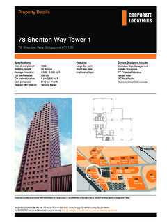
2 This feature also providesseparation of and circuits. Double-break contacts openthe circuits in two places, creating two air gaps and reducing theprobability of welded contacts by more that 50% compared to a single-break IdentificationThe red faceplate allows easy identification of safety devices. This face place displays the IEC 60947-5-1 mechanically-linked anti-tamper feature ensures the long-term integrity of yoursafety system. All contact blocks are permanently fixed to ensurethat the safety function is not jeopardized. Manual operation andfield modifications are ProfileSafety Control RelaysDesigned To Meet Worldwide Safety Standards700S-CF (8 pole) 700S-P (4 12 pole)IEC mechanically-linked symbolDouble-break contactsreduce the probability of awelded 700s -CFSafety Control Relays0 Bulletin 700S-CF Positively guided/mechanically linked contacts Mechanically-linked contacts symbol prominently displayed on front Red face plate 8 poles, all permanently attached Ideal for use in safety circuits AC and DC operating coils SUVA third-party certificationTABLE OF CONTENTSD escriptionPageDescriptionPageProduct Selection.
3 4 Dimensions .. 7 Specifications ..5 DescriptionBulletin 700S-CF Safety Control Relays provide mechanically linked, positively guided contacts, which are required in feedback circuits for modern safety applications. The positively guided auxiliary contacts will not change state if a contact welds. Use with safety relays to expand output order must include: Cat. No. of the relays required, complete with coil suffix. Cat. No. of adder decks, timers and accessories required. If required, the part number of replacement to StandardsApprovalsIEC 947-5-1CE CertifiedEN 50011, EN 50005, EN 50022 CSA Certified UL 508UL Listed, File E14840, Guide NKCRVDE 0660 SUVA Third Party CertifiedCSA Part 14 Bulletin 700s -CFSafety Control Relays4 Product SelectionType S-CF Safety Control Relays 8-Pole AC and DC Coil Voltages AC Coil Voltage Suffix Code DC Coil Voltage Suffix Code When ordering DJ coil with built-in surge suppression, remove Z from the Cat.
4 No. Example: Cat. No. 700s -CF440Z C becomes Cat. No. DiagramsContacts700S-CFAC CoilsDC CoilsMainContactsAuxiliary ContactsCat. No. Cat. No. C700S-CF620Z C53700S-CF530 C700S-CF530Z C44700S-CF440 C700S-CF440Z C35700S-CF350 C700S-CF350Z CVoltage122432364248100100-1101101201272 00200-220208208-240220-23050 HzRKVWXYKP DPSKG F60 HzQJ V X KP D KGHL 50/60 Hz KJ KYKP KD KG Voltage230230-240240277347380380-4004004 00-41544048050055060050 Hz VAT N GB MC 60 Hz ATIE NB C50/60 HzKF KA KN KB Voltage912243648606472801101151252202302 50 StandardRQJWYZBGEDPSAFTWith diode suppressor DJ 3334K15453626174738483545362617473848354 536261747384833334K154536261727184833334 K154536261727182813334K15 Bulletin 700s -CFSafety Control RelaysSpecificationsGeneral For sixteen or more strands, end ferrule is required. Defined in IEC 947-5-1 annex L. Mechanically-linked is a relationship between contacts of opposite types ( , and ).
5 If the accessory is a pneumatic timer or latch, there is no mechanically-linked guidance; the accessory contacts are independent. Cat. No. 700s -CFmain poles front auxiliary contactsContact Ratings NEMAA600, P600A600, Q600UL General Purpose Current20A!0 AMinimum Contact Rating17 mA20 24V20 mAContact Ratings IEC AC-15 (solenoids, contactors) at rated voltageIEC 947, EN 6094724V15 A6 A48V15 A6 A120V14 A6 A240V10 A5 A400/415V5 A3 A480 A690V1 AAC-12 (Control of AC resistive loads)IEC 947, EN 6094740 CIth20 A10 A230V10 kW400V17 kW690V30 kW60 CIth20 A6 A230V8 kW400V14 kW690V24 kWDC-12(Control of DC resistive loads)IEC 947EN 6094724V12 A12 A48V9 A9 ADC-13 IEC 947, EN 60947, Solenoids and contactors24V5 A5 A48V2 A2 AAvg-Mechanical Life (ops)[Mil]1515 Average-Electrical Life(ops)AC-15 (240V, 3 A)[Mil] Cross-SectionsTerminal TypeTerminal Size per IEC 947-12 x A42 x A4 Solid/Stranded 1 or 2 Conductor Conductor[mm2][mm2] Wire Size per UL/CSA[AWG] Torque[ ] Torque[N m] Location of welded contactsState of Contacts if contact weldsMain Front side side OpenOpenFront OpenOpenLeft side OpenOpenRight side OpenOpen Mechanically -linked Contacts Bulletin 700s -CFSafety Control Relays6 Specifications, ContinuedControl Circuit For 9V DC, code ZR, use operating voltage x Us.
6 For 24V DC, code ZJ or DJ, use operating voltage x 8 kV for main poles, 6 kV for front aux. contacts. 40 degree max. for 700s -CF350 with DC coil. Operation in 70 C ambient is permitted with current reduction of 15% below rated valuesCat. No. 700s -CFOperating VoltageAC 50/60 HzPickup[x Us] [x Us] Pickup[x Us] [x Us] Consumption at nominal voltageAC 50/60 HzInrush [VA/W]70/50 Seal [VA/W]8 warm coil[W] cold coil[W] TimesAC 50/60 HzPickup Time[ms] Time[ms] Time[ms] Time[ms] integrated suppression[ms] diode suppression[ms] No. 700s -CFRated Insulation Voltage UiIEC690 VUL; CSA600 VDielectric Withstand Voltage2500 VRated Impulse Strength Uimp8 kV Rated Voltage UeAC115, 230, 400, 500, 690 VDC24, 48, 110, 220, 440 VShort-Circuit Protection IEC 947-5 Fuse-Type GG20 ARated Frequency50/60 Hz, DCAmbient TemperatureStorage +80 C ( F)Operation at nominal current +60 C ( F) Corrosion Resistancehumid-alternating climate, cyclic, per IEC 68-2-30 andDIN 50 016, 56 cyclesAltitude2000 m above mean sea level, per IEC 947-4 Type of ProtectionIP2X in connected stateFinger Protectionsafe from touch by fingers and back of hand per VDE 0106, Part 1007 Bulletin 700s -CFSafety Control RelaysDimensionsAC Safety Control RelaysDC Safety Control Relays All Cat.
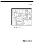
7 Nos. are factory Positionsabcc1c2 dd1 d2 Cat. No. 45(1-25/32)81(3-3/16) (4-3/4) (4-43/64)6(1/4)2 - (2 - 3/16)60(2-23/64)35(1-25/64) 700s -CFabcc1c2 dd1 d2 Cat. No. 45(1-25/32)81(3-3/16) (5-49/64) (5-37/64)6(1/4)2 - (2 -3/16)60(2-23/64)35(1-25/64) 700s -CFSafet y Control Relays withmm(inches)Auxiliary contact block for side mounting 1- or 2-polea + 9(a + 23/64)Electronic Timing Module on coil terminal sideb + 24(b + 15/16)Mechanical Interlock on side of contactora + 9(a + 23/64)Interface Module on coil terminal sideb + 9(b + 23/64)Surge Suppressor on coil terminal sideb + 3(b + 1/8)Labeling with label sheetmarking tag sheet with clear covermarking tag adapter for System Bul. 1492W+ 0+ 0+ (+ 0)(+ 0)(+ 7/32)c2cc1 Mounting PositionAC Safety Control RelaysDC Safety Control RelaysBulletin 700s -PSafety Control Relays80 Bulletin 700S-P Mechanically-linked contacts meeting IEC 947-5-1-L poles all mechanically-linked Red faceplate for easy identification of safety circuits IEC mechanically-linked contacts symbol displayed on front Double-break contacts to reduce probability of welded contacts Visual indication of contact state Tamper resistant Lexan cover helps prevent changes which could jeopardize safety Complete catalog number displayed on front Ideal for use in safety circuitsTABLE OF CONTENTSD escriptionPageDescriptionPageProduct Selection.
8 9 Specifications .. 10 Approximate Dimensions..11 Description The 700S-P safety control relay is designed with special features for use in safety circuits. It is designed to reduce the possibility of a welded contact, and, with external monitoring, a welded contact can be detected if one ever occurs. It features mechanically linked contacts for all contact pairs which allow detection of a welded contact in any of the poles. Contacts cannot be added, removed, nor changed so that the safety function is never jeopardized. Similarly, there is no push-to-test function so that safety function is not jeopardized. Typical applications: use with E-stops, light curtains, safety gates, safety order must include: Cat. No. of the relays required, complete with coil to StandardsApprovalsNEMA ICS-5-2EN/IEC 60947-5-1, including Mechanically-linked ContactsIEC 337-1 CENELECBS 4794 cULus ListedVDE 0660UL File #E14840, Guide NKCRCSA No.
9 14 ANSI , section , Control ReliabilityUL508CE Certified9 Bulletin 700s -PSafety Control RelaysProduct SelectionType S-P Safety Control Relays AC and DC Coil Voltages For other coil voltages, consult your local Allen-Bradley Sales Office. For other coil voltages, consult your local Allen-Bradley Sales Office. AC Voltage Suffix CodeThe Cat. No. as listed is incomplete. Select a voltage suffix code from the table below to complete the Cat. No. Example: Cat. No. 700s -P310 becomes Cat. No. 700s -P310A1 for a 120V AC coil. Connection Diagrams and terminal markings ContactsAC Coils24V DC CoilsCoil and Main ContactsAdditional ContactsAdditional ContactsCat. No. Cat. No. 31700S-P310 700s -DCP310Z24 22700S-P220 700s -DCP220Z24 71700S-P710 700s -DCP710Z24 62700S-P620 700s -DCP620Z24 53700S-P530 700s -DCP530Z24 44700S-P440 700s -DCP440Z24 35700S-P350 700s -DCP350Z24102700S-P1020 700s -DCP1020Z24Hz24115-120230-240277460- 48060A24A1A2A27A4A1XA1YA2XA2YA3XA3YA4XA4 YK1K2A1XA1YA2XA2YA3XA3YA4XA4YK1K2A1XA1YA 2XA2YA3XA3YA4XA4YK1K2B1XB1YB2XB2YB3XB3YB 4XB4YA1XA1YA2XA2YA3XA3YA4XA4YK1K2B1XB1YB 2XB2YB3XB3YB4XB4YA1XA1YA2XA2YA3XA3YA4XA4 YK1K2B1XB1YB2XB2YB3XB3YB4XB4YA1XA1YA2XA2 YA3XA3YA4XA4YK1K2B1XB1YB2XB2YB3XB3YB4XB4 YA1XA1YA2XA2YA3XA3YA4XA4YK1K2B1XB1YB2XB2 YB3XB3YB4XB4YA1XA1YA2XA2YA3XA3YA4XA4YK1K 2B1XB1YB2XB2YB3XB3YB4XB4YC1XC2XC3XC4XC1Y C2YC3YC4 YBulletin 700s -PSafety Control Relays10 Specifications Coil voltage required for proper operation (percent of rated coil voltage).
10 Temperature inside the panel. 90% of devices are expected to meet or exceed million operations, and 50% of devices are are expected to meet 20 million Rating Continuous10 A @ 600V AC5 A @ 600V DCRatingsMake/BreakACNEMA A600 DCNEMA P600 Minimum Contact Switching Ratings 10V, 50 mADC SwitchingContactsin SeriesVo l ts D C246412525050060015 A A210 A 10 A5 A2 A .5 A3 7 A3 A A4 10 A5 A AContact Electrical Life Resistive million operations at 10A break at 120V AC14 million operations at 1A break at 120V AC6 million operations at 1A break at 24V DCCoil Voltage Range Consumption50 Hz60 HzACInrush132 VA138 VA19 WMechanicalMechanically Linked ContactsAll contacts are mechanically linked per IEC 947-5-1 annex L for 2 to 12 polesOperating TimePickupAC msDC msDropoutAC msDC msMechanical million operations ConstructionContact Arrangement2 to 12 Poles, Double Break or (8 Maximum) Contact Material/DesignSilver Nickel/BifurcatedMountingPanel mount or mount on 700-MP RailHorizontal Mounting RecommendedEnvironmentalTemperature Operating +65 C ( F)Storage +65 C ( F)Wire TerminationsWire size per UL/CSA1X #18 #12 AWGT ightening lb-in.