Transcription of Bulletin E-111 Series 626 & 628 Pressure Transmitters
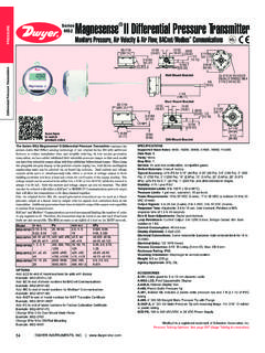
1 Bulletin E-111 . Series 626 & 628 Pressure Transmitters . Specifications - Installation and Operating Instructions -CH Conduit Housing -GH General Purpose Housing LIQUID TIGHT FITTING. CORD DIAMETER RANGE 1-9/32..200 to .350 ( to ) [ ]. 055/64 [ ]. 1/4 NPT. 1-3/32. [ ] 2-15/16 [ ]. OPTIONAL 1/4 NPT. FEMALE FITTING. 3-1/2 [ ] 7/8 [ ]. 1/4 NPT HEX 2-27/64 [ ]. MALE FITTING. 1/4 NPT 3-13/64 [ ]. 3/4. [ ]. 5-1/2 [ ]. The Series 626 & 628 Pressure Transmitters converts a single positive Pressure SPECIFICATIONS. into a standard 4 to 20 mA output signal. The Series 626 and 628 can be used to Service: Compatible gases and liquids. Loop Resistance: 0-1000 Ohms max. accurately measure compatible gases and liquids; Series 626 full scale accuracy Wetted Materials: Type 316 SS. R max = 50 (Vps-10) Ohms (4 to 20 mA. is ; Series 628 full scale accuracy is (see specifications).)
2 Designed for Accuracy: 626: FS, RSS; output), 5K Ohms (0-5, 1-5, 1-6, 0-10, industrial environments with a NEMA 4X (IP66) housing, this transmitter resists most 628: FS, RSS; 626 absolute 2-10, VDC output). effects of shock and vibration. ranges: FS, RSS. (Includes Current Consumption: 38 mA. linearity, hysteresis, and repeatability). maximum (for 4 to 20 mA output); 10 mA. Temperature Limit: 0 to 200 F (-18 to maximum (for 0-5, 1-5, 1-6, 0-10, 2-10, Caution: Do not exceed specified supply voltage ratings. Permanent 93 C). VDC output); 140 mA maxumum damage not covered by warranty will result. This device is not designed Compensation Temperature Range: 0 (for all 626/628/629-CH with optional for 120 or 240 volt AC operation. Use only on 13 to 30 VDC. to 175 (-18 to 79 C). LED). Thermal Effect: 626: FS/ F. Electrical Connections: Conduit 628: FS/ F (includes zero and Housing (-CH): terminal block, 1/2.
3 Pressure Ranges span). female NPT conduit; General Purpose Pressure Maximum Over Pressure Limits: See table. Housing (-GH): cable DIN EN 175801- Range Pressure Pressure Power Requirements: 10-30 VDC (for 803-C. 0-15 psia 30 psia 45 psia 4 to 20 mA, 0-5, 1-5, 1-6 VDC outpus); Process Connection: 1/4 male or 15-0 psia 30 psia 45 psia 13-30 VDC (for 0-10, 2-10 VDC outputs); female NPT and BSPT. 0-30 psia 60 psia 90 psia 5 VDC VDC (for VDC ratio- Enclosure Rating: NEMA 4X (IP66). 0-50 psia 100 psia 150 psia metric output). Mounting Orientation: Mount in any 0-100 psia 200 psia 300 psia Output Signal: 4 to 20 mA, 0-5 VDC,1-5 position. 0-200 psia 400 psia 600 psia VDC, 0-10 VDC, or VDC. Weight: 10 oz (283 g). 0-300 psia 600 psia 900 psia Response Time: 300 ms. Agency Approvals: CE. 0-5 psig 10 psig 50 psig 0-15 psig 30 psig 150 psig INSTALLATION.
4 0-30 psig 60 psig 300 psig 1. Location: Select a location where the temperature of the transmitter will be 0-50 psig 100 psig 300 psig between 0 and 175 F (-18 to 79 C). Distance from the receiver is limited only by 0-100 psig 200 psig 500 psig total loop resistance. The tubing or piping supplying Pressure to the unit can be 0-150 psig 300 psig 750 psig practically any length required but long lengths will increase response time slightly. 0-200 psig 400 psig 1000 psig 0-300 psig 600 psig 1500 psig 2. Position: The transmitter is not position sensitive. However all standard models 0-500 psig 1000 psig 2500 psig are originally calibrated with the unit in a position with the Pressure connection 0-1000 psig 2000 psig 5000 psig downward. Although they can be used at other angles, for best accuracy it is 0-1500 psig 3000 psig 5000 psig recommended that units be installed in the position calibrated at the factory.
5 0-2000 psig 4000 psig 5000 psig 0-3000 psig 6000 psig 7500 psig 3. Pressure Connection: Use a small amount of plumber's tape or other suitable 0-5000 psig 7500 psig 10000 psig sealants to prevent leaks. Be sure the Pressure passage inside the port is not 0-8000 psig 10000 psig 12000 psig blocked. 4. Electrical Connections Wire Length - The maximum length of wire connecting the transmitter and receiver is a function of wire size and receiver resistance. Wiring should not contribute more than 10% of the receiver resistance to total loop resistance. For extremely long runs (over 1000 feet), choose receivers with higher resistance to minimize the size and cost of connecting leads. Where wiring length is under 100 feet, wire as small as 22 AWG can be used. DWYER INSTRUMENTS, INC. Phone: 219/879-8000 BOX 373 MICHIGAN CITY, INDIANA 46360, Fax: 219/872-9057 e-mail: CURRENT (4 to 20 mA) OUTPUT OPERATION PRESS AND HOLD TO PRESS TO.
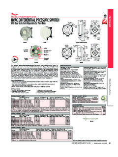
6 An external power supply delivering 10-30 VDC with minimum current capability of ZERO THE DISPLAY DISPLAY. 40 mA DC (per transmitter ) is required to power the control loop. See Figure A for SPAN THE GAGE'S. connection of the power supply, transmitter and receiver. The range of appropriate ZERO Pressure . RANGE. receiver load resistance (RL) for the DC power supply voltage available is expressed by the formula: RL Max = Vps 10. 20 mA DC. POWER. SUPPLY RECEIVER TERM 1 (+). +. 1 RED mA. 10-30 VDC. POWER (40 ma) - TERM 2 (-). RECEIVER. Pressure 2 BLACK SUPPLY LED DISPLAY CONNECTOR. transmitter mA 13-30 VDC - LED DISPLAY TERM 3 (-). 10-30 VDC NEGATIVE SUPPLY. 3 (NC) 4 SILVER (100 ma) + LED DISPLAY TERM 4 (+) YELLOW. POSITIVE SUPPLY. LED SUPPLY. POWER SUPPLY. SHIELD WIRE (NOT CASE GROUNDED). transmitter CONNECTION: Figure A: Current output connection - TURN OFF POWER.
7 - CONNECT THE POWER SUPPLY. AND RECEIVER TO TERM 1 AND. Conduit Housing with 4 to 20 mA Output (-CH) Electrical connections to the Pressure TERM 2 OF THE GAGE AS SHOWN OPTIONAL LED DISPLAY. Transmitters are made to the terminal block located inside the housing. Remove the - CONNECT LED POWER SUPPLY (-). TO TERMINAL 3. screws and lift off the cover. Wire as shown in Figure A, B or C. Use Figure A for - CONNECT LED POWER SUPPLY (+) BE SURE TO TURN OFF POWER WHEN. current output connection. Use Figure B for current output with optional LED display. TO TERMINAL 4 CONNECTING OR REMOVING THE. Use Figure C for current output with optional LED display using two power supplies. - INSTALL THE DISPLAY'S CONNECTOR DISPLAY'S CONNECTOR. FAILURE TO DO. - TURN ON POWER SO CAN RESULT IN THE GAGE DAMAGE. If ordering optional pre-wired cable, black wire is negative (-) and red wire is positive (+).
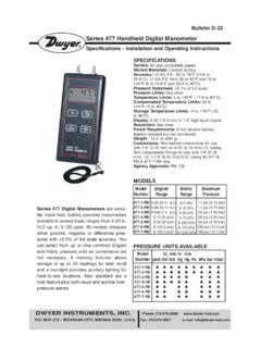
8 Figure C: Current output with optional LED display using two power supplies PRESS AND HOLD TO PRESS TO Hirschman DIN Connector with 4 to 20 mA When using cable version of -GH. ZERO THE DISPLAY DISPLAY General Purpose Housing, black wire is negative (-) and red wire is positive (+). When THE GAGE'S. SPAN Pressure using optional Hirschman DIN Plug, remove top-center screw and lift off the terminal ZERO RANGE block assembly. Wire to terminals shown below in Figure D. For optional 4-pin M-12. connector, wire to pins as shown in Figure E. A. POWER. SUPPLY TERMINAL 4: (-). TERMINAL 3: RECEIVER TERM 1 (+) TERMINAL 1: (+) (GROUND). +. 10-30 VDC. (140 ma) mA TERM 2 (-). - SECTION A-A. LED DISPLAY CONNECTOR TERMINAL 1: (+). TERMINAL 2: (-). A. LED DISPLAY TERM 4 (+) YELLOW. POSITIVE SUPPLY Figure D Figure E. 55/64. 1/4 NPT [ ]. transmitter CONNECTION: A; [-] A; [-].
9 - TURN OFF POWER B; [+] B; [+]. - CONNECT THE POWER SUPPLY OPTIONAL LED DISPLAY. AND RECEIVER TO TERM 1 AND. TERM 2 OF THE GAGE AS SHOWN. - CONNECT POWER SUPPLY (+) TO C; [GND] C; [Vout +]. TERMINAL 4 (REQUIRED FOR THE BE SURE TO TURN OFF POWER WHEN 7/8. OPTIONAL DISPLAY ONLY) CONNECTING OR REMOVING THE 2-27/64 [ ] [ ]. - INSTALL THE DISPLAY'S CONNECTOR DISPLAY'S CONNECTOR. FAILURE TO DO HEX. - TURN ON POWER SO CAN RESULT IN THE GAGE DAMAGE. 3-5/16 [ ]. Figure B: Current output with optional LED display connection Figure F: Packard Connection VOLTAGE (0-5, 1-5, 0-10, 1-6 or 2-10 VDC) OUTPUT OPERATION RATIOMETRIC ( VDC) OUTPUT OPERATION. (Other outputs contact the factory) See Figure G for connection of the power supply, (Other outputs contact the factory) See Figure K for connection of the power supply, transmitter and receiver. transmitter and receiver.
10 1 RED 1 RED. POWER. Pressure 2 BLACK (COMMON) POWER 2 BLACK (COMMON) SUPPLY. transmitter SUPPLY Pressure 5 VDC. transmitter 10%. 3 WHITE (+V OUT) 3 WHITE (+V OUT). 4 SILVER 4 SILVER. V IN V IN. RECEIVER SHIELD WIRE RECEIVER SHIELD WIRE. (NOT CASE GROUNDED) (NOT CASE GROUNDED). Figure G: Voltage output connection Figure K: Voltage output connection Conduit Housing (-CH) Electrical connections to the Pressure Transmitters are General Purpose Housing with Ratiometric Output When using cable version of made to the terminal block located inside the housing. Remove the screws and lift -GH General Purpose Housing, black wire is negative (-), red wire is positive (+) and off the cover. Wire as shown in Figure G or Figure H. Use Figure G for voltage output white wire is output. When using optional Hirschman DIN Plug, remove top-center connection.