Transcription of Bulletin No. PAXCDL-D Drawing No. LP0401 Tel +1 …
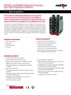
1 ORDERING INFORMATIONINSTALLING AN OPTION CARDC aution: The option and main circuit cards contain staticsensitive components. Before handling the cards, dischargestatic charges from your body by touching a grounded baremetal object. Ideally, handle the cards at a static controlledclean workstation. Also, only handle the cards by the edges. Dirt,oil or other contaminants that may contact the cards canadversely affect circuit : Exposed line voltage exists on the circuit all power to the meter AND load circuits beforeaccessing the Remove the main assembly from the rear of the case.
2 Squeeze the fingerholds on the rear cover, or use a small screwdriver to depress the sidelatches to release it from the case. It is not necessary to separate the rearcover from the main circuit Locate the option card connector for the type of option card to beinstalled. Hold the unit by the rear connector, not the display board, wheninstalling an option Install the option card by aligning the option card connector with the slotbay in the rear cover. The cards are keyed by position with different mainboard connector locations.
3 Be sure the connector is fully engaged and thetab on the option card rests in the alignment slot on the display Slide the assembly back into the case. Be sure the rear cover latches fullyinto the Apply the option card label to the bottom side of the meter. Do not coverthe vents on the top surface of the surface of the case mustbe clean for the label to adhere properly. Apply the label to the areadesignated by the large case Bulletin serves as a guide for the installation, configuration andoperation of the PAX Analog Output card.
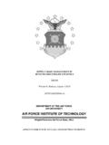
4 The analog output can beconfigured for 0 to 20 mA, 4 to 20 mA or 0-10 VDC. Only one range can beused at a PAX meter can be fitted with up to three optional plug-in cards. Theslot bays of the plug-in cards are dedicated to a particular card function. Theplug-in card functions are: serial communications, analog output and setpointoutput. Only one card from each function category can be PAXCDL -ANALOG OUTPUT PLUG-IN OPTION CARDSPECIFICATIONSA nalog Output Card Types: 0 to 20 mA, 4 to 20 mA and 0 to 10 VDCI solation To Sensor & User Input Commons: 500 Vrms for 1 Voltage: 50 V.
5 Not isolated from all other Only:Isolation To Sensor Common: 1400 Vrms for 1 Voltage: 125 VIsolation To User Input Common: 500 Vrms for 1 Voltage: 50 VAccuracy: of FS (18 to 28 C); of FS (0 to 50 C)Resolution: 1/3500 Compliance:10 VDC: 10 K load mA: 500 load max. (self-powered)Update Time: 200 msec. max. to within 99% of final readout value (digitalfilter and internal zero correction disabled)700 msec. max. (digital filter disabled, internal zero correction enabled)PAXH only: 1 sec. max. to within 99% of final readout value (digital filterdisabled)MODEL NUMBERPAXCDLA nalog Output CardPAXCDL10 TOP VIEWB ulletin No.
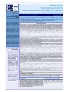
6 PAXCDL-DDrawing No. LP0401 Released 3/08 Tel +1 (717) 767-6511 Fax +1 (717) the analog output type. For 0-20 mA or 4-20 mAuse terminals 18 and 19. For 0-10 V use terminals 16 and17. Only one range can be used at a time. ANALOG TYPEANALOG ASSIGNMENT SELECTION0 to 10 V4 to 20 mA0 to 20 mARANGE Enter the Display Value that corresponds to 0 mA (0-20mA) , 4 mA (4-20 mA) or 0 VDC (0-10 VDC). ANALOG LOW SCALE VALUE ANALOG HIGH SCALE VALUEANALOG UPDATE TIMEPROBE BURN-OUT ACTION (PAXT ONLY) to to to MODULE 8 - Analog Output Parameters ( )PARAMETER MENUI ndicates Program Mode Alternating Settings are shown.
7 Parameter Selection/ValueLIMITED WARRANTYThe Company warrants the products it manufactures against defects in materials and workmanshipfor a period limited to two years from the date of shipment, provided the products have been stored,handled, installed, and used under proper conditions. The Company s liability under this limitedwarranty shall extend only to the repair or replacement of a defective product, at The Company soption. The Company disclaims all liability for any affirmation, promise or representation withrespect to the customer agrees to hold Red Lion Controls harmless from, defend, and indemnify RLC againstdamages, claims, and expenses arising out of subsequent sales of RLC products or productscontaining components manufactured by RLC and based upon personal injuries, deaths, propertydamage, lost profits, and other matters which Buyer, its employees, or sub-contractors are or may beto any extent liable.
8 Including without limitation penalties imposed by the Consumer Product SafetyAct ( 92-573) and liability imposed upon any person pursuant to the Magnuson-Moss WarrantyAct ( 93-637), as now in effect or as amended warranties expressed or implied are created with respect to The Company s products except thoseexpressly contained herein. The Customer acknowledges the disclaimers and limitations containedherein and relies on no other warranties or the source for the analog output to retransmit: = Display Input Value = Maximum Display Input Value = Minimum Display Input Value = Totalize Display ValueEnter the Display Value that corresponds to 20 mA (0-20mA) , 20 mA (4-20 mA) or 10 VDC (0-10 VDC).
9 Enter the analog output update rate in seconds. A valueof allows the meter to update the analog output at arate of 20 the probe burn-out action. In the event of atemperature probe failure, the analog output can beprogrammed for low or high Lion Controls 20 Willow Springs CircleYork PA 17406 Tel +1 (717) 767-6511 Fax +1 (717) 764-0839 Red Lion Controls APUnit 101, XinAn PlazaBuilding 13, Tianzhou RoadShangHai, China 200223 Tel +86 21 6113-3688 Fax +86 21 6113-3683 Red Lion Controls BVPrinterweg 10NL - 3821 AD AmersfoortTel +31 (0) 334 723 225 Fax +31 (0) 334 893 793