Transcription of BV Operating Manual - vibtec.com
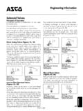
1 BV. PNEUMATIC PISTON VIBRATORS. Operating Manual . Technical Characteristics Piston Dia. Weight Hopper Wall Capacity in Sloping Model mm Kgs mm Section BV 112 28 m3. BV 150 38 m3. BV 225 57 m3. BV 312 80 m3. BV 425 108 m3. BV 650 165 & Up m3. IMPORTANT NOTICE. Vibrators and vibrating equipment can be dangerous if not used correctly. 1. DO NOT hold or touch when running. 2. DO NOT stand or sit on vibratory equipment when running. 3. USE ONLY for the purpose intended. 4. USE ONLY when vibrators are securely mounted. 5. USE ONLY when pneumatic hoses and fittings are securely tightened. 6. ALWAYS wear ear protectors. We reserve the right to improve, modify or withdraw specifications or products without notice or obligation. Operating AND MAINTENANCE instructions . Installation 1. Attach to hopper using mounting plate or channel. 2. Stitch weld mounting plate to hopper, leaving ends free of weld for approx.
2 20mm. 3. Check that plate is flat after welding. 4. Use high tensile bolts (quality - DIN 931-933) sized accordingly to vibrator fixing holes. 5. Re-tighten all fixings after one hour of operation, then periodically thereafter. 6. If a single vibrator is used then position approx. one third up inclined face. When 2, 3 or more are used then space equally and stagger up the side of the hopper. 7. All vibrators that incorporate safety eyes for safety cables, should be used. 8. In most cases, continuous vibration is not necessary, short bursts will overcome the problem, which can be achieved by using a pneumatic or electric cyclic timer. Pneumatic supply 1. The BV piston vibrators require a lubricated and filtered air supply. For continuous operation a simple on/off valve may be used, for single impact then a 3 port 2 way valve must be used; in both cases the valve must open quickly. See the back page for guidance on converting between single and continu- ous impacting.
3 2. Check and set air pressure for most effective vibrator operation; permitted range 2 to 6 bar. 3. Check lubricator level and if necessary add oil, SAE 10 or lighter. In extremely cold conditions, mix anti-freeze or paraffin with oil. 4. Periodically check all air connections and tighten if necessary. 5. Check air line filter and drain bowl. 6. Ensure vibrator interior is well lubricated if it is to be shut off for a long period of time. Trouble shooting Vibrator does not operate: 1. Check for adequate air pressure and flow. 2. Check whether mounting plate surface is flat. 3. Check that Operating valve is opening quickly and located within 3m of the vibartor. 4. Check for broken spring. Vibrator sluggish or slow to start: 1. Check interior for air line contamination. 2. Check for proper lubrication. 3. Check for defective Operating valve. 2. Models BV 312,425 and 650 Models BV 112, 150 and 225.
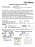
4 Dimensions (mm). Model A B C D E F G H. BV 112 1/4'' BSP. BV 150 1/4'' BSP. BV 225 1/4'' BSP. BV 312 3/8'' BSP. BV 425 1/2'' BSP. BV 650 1/2'' BSP. Single Impacting Force ( ). Model 2 Bar 4 Bar 6 Bar BV 112 BV 150 BV 225 BV 312 BV 425 BV 650 Continuous Impacting 2 Bar (30 psi) 4 Bar (60 psi) 6 Bar (88 psi). Model Force Freq. Air Force Freq. Air Force Freq. Air (Kgs) VPM L/min (Kgs) VPM L/min (Kgs) VPM L/min BV 112 4450 26 6200 57 7850 126. BV 150 3175 52 128 4600 98 182 5500 166. BV 225 144 2800 115 235 3600 172 318 4200 207. BV 312 314 2175 215 546 2900 301 787 3500 344. BV 425 474 1525 221 759 1950 373 1137 2400 451. BV 650 1319 975 708 2818 1425 1584 4525 1875 2605. 3. Converting from single to continuous impacting The BV range of impacting linear vibrators are supplied for single impacting' using air inlet port in top plate. If continuous impacting is required, they can be easily converted by using the alternative air inlet port on the side and plug the top port.
5 Also remove the top exhaust plug that has a small bleed hole as shown below. 2 CHAPEL ROAD, PORTSLADE, BRIGHTON, BN41 1PF ENGLAND. Tel. +44(0) 1273 430977 Fax. +44 (0) 1273 430978. Web. E-mail.