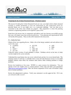
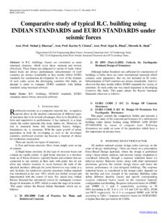
Transcription of By MALORY GOODING University of Cincinnati April 17, 2017
1 Page 1 of 7 AN OVERVIEW OF LATERAL FORCE resisting SYSTEMS By MALORY GOODING University of Cincinnati April 17, 2017 Page 2 of 7 EXECUTIVE SUMMARY Every structure must be designed for lateral loads. However, lateral loads are typically less predictable, with load paths more difficult to track than vertical loads. They are often conceptually hard to grasp but important to understand for a structural engineer. This paper will give an overview of lateral force resisting system design concepts for wind and seismic loading, including a review of lateral force resisting elements, diaphragms, and practical considerations in their design. BASIC LATERAL FORCE resisting ELEMENTS Every structure must incorporate vertical elements to transfer lateral loads, including wind, seismic, and stability forces, through floor or roof diaphragms to the building foundation.
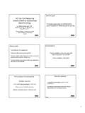
2 A few common systems are listed below. Steel moment frames are vertical frames with rigid joints and flexible members. They resist lateral loads through flexural strength (bending) of members and continuity of columns and beams through rigid connections (Figure 1). Moments are transferred from beams to columns at rigid connection points (Figure 2). Concrete frames are typically considered moment frames due to the inherent continuity of monolithic construction. Figure 1: Steel Moment Connection Figure 2: Bending Moment Diagram (Figure 1) "Analysis of Frames." Analysis of Frames| , Web. 14 Apr. 2017. (Figure 2) Amstead, Robert. "Seismic Retrofit Lessons Learned: Technical.
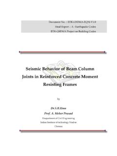
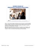
3 " Seismic Retrofit Lessons Learned: Technical - Buildipedia. , Web. 16 Apr. 2017. Shear walls, usually concrete or masonry, resist lateral forces as a vertical diaphragm through in-plane shear (Figure 3). These walls are usually long compared to their height, utilizing in-plane stiffness and acting as a vertically spanning beam to resist lateral forces (Figure 4). Flexure is resisted by vertical reinforcement along the wall. It is important to consider openings when calculating a wall s shear capacity, because wall sections with openings will be the weakest path Page 3 of 7 of shear resistance. Walls above and below openings act as tie beams that distribute load between shear walls (Figure 5).
4 To fully transfer shear forces into substructure, wall vertical bars must be adequately lapped with foundation dowels. For in-plane shear, the wall acts as a cantilevered beam that is fixed at the base. Figure 3: Concrete Shear Walls Industrial Process Facilities. Tindall, Web. Figure 4: Shear Wall Deflection Figure 5: Shear Wall with Openings (Figure 4) "Lateral Load- resisting Systems." Reinforced Concrete Design of Tall Buildings (2009): 199-252. Web. (Figure 5) "Lateral Load- resisting Systems." Reinforced Concrete Design of Tall Buildings (2009): 199-252. Web. Page 4 of 7 Braced frames resist lateral loads by the transfer of axial forces (tension or compression) through diagonal bracing members (Figure 5).
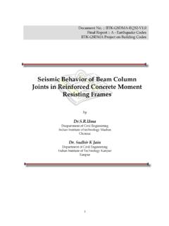
5 These braces transfer forces from roof or floor diaphragms through shear connections and down to the foundation. There are two basic types of braced frames: concentric and eccentric. Concentric frames have braces connecting at the ends of elements. This develops truss action, creating a relatively stiff frame to resist lateral loads. A few common configurations are cross-bracing, v-bracing, and single diagonal braces (Figure 6). Eccentrically braced frames utilize diagonal braces with one or two ends joining eccentric to the supporting member. This essentially creates a braced frame with increased ductility, similar to a moment frame. These are more commonly used in high seismic regions (Figure 7) (Lateral).
6 Figure 5: Braced Frame "BRBF Steel Design and Bozeman s Mill Street Lofts." , Web. Figure 6: Concentrically Braced Frames "Braced Frames." Braced Frames Seismic Resilience. Seismic Resilence, Web. 14 Apr. 2017 Figure 7: Eccentrically Braced Frames "Braced Frames." Braced Frames Seismic Resilience. Seismic Resilence, Web. 14 Apr. 2017 Page 5 of 7 ROOF AND FLOOR DIAPHRAMS Lateral wind loads are transferred to the wind force resisting system through roof and floor diaphragms. The diaphragm essentially acts as a deep beam spanning between vertical lateral framing members or bracing bays. It drags parallel wind pressure from the roof and walls into the lateral force resisting system (Figure 8).
7 Figure 8: Diaphragm Deflection from Applied Lateral Loads "Chapter 9: Horizontal Diaphragms." Chapter 9: Horizontal Diaphragms | Engineering360. IEEE GlobalSPEC, Web. 14 Apr. 2017. Diaphragms can be idealized as flexible or rigid. The difference between the two is relative stiffness, which affects how the diaphragm distributes lateral loads. Flexible diaphragms distribute lateral loads to vertical members based on tributary area, similar to vertical load distribution in a structure. Load is transferred only to members with strong axis oriented parallel to lateral load direction. Members with strong axis oriented perpendicular to the loading direction are assumed to not contribute.
8 In a rigid diaphragm, loads are distributed based on relative stiffness of vertical members oriented in any direction (Fanella). It is important to consider torsion for rigid diaphragms, as it cannot be simply resisted through bending of the diaphragm elements. Connections between diaphragms and lateral resisting elements are crucial. They must be able to transfer axial and shear loads in both tension and compression to provide frame continuity. Typically, wood or steel diaphragms are considered flexible, while a concrete roof diaphragm is considered rigid. However, the relative stiffness of the diaphragm compared to the relative stiffness of the vertical elements affect how a diaphragm behaves.
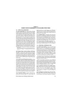
9 For example, if the lateral resisting system is a flexible moment frame, the diaphragm will behave more rigidly than if the lateral resisting system were constructed of concrete shear walls (Wilson). It is wise to utilize finite elements analysis when evaluating complicated structures, such as those with irregular geometry, or structures utilizing multiple load resisting systems and materials. Simplified load distribution assumptions will not be as accurate for these situations. Page 6 of 7 PRACTICAL CONSIDERATIONS How is a lateral force resisting system chosen during design? In practice, economics and building program most often determine the lateral bracing system, but life safety and fire rating must also be considered (Wilson).
10 For example, a steel braced frame is more economical than a steel moment frame. Steel moment frames require heavy connections as well as relatively higher material and labor costs. However, if a building requires a completely open layout, walls with large windows, or has inadequate clearance for steel bracing, a more expensive moment frame may be required. Sometimes, it is clear which lateral system is the best for a particular structure. Consider a large concrete parking garage. Engineers often use concrete shear walls, which fit on column lines and can tie monolithically to the structure. In many buildings, elevator shaft walls which are already required are utilized as shear walls. If reinforced masonry walls are used within the structure architecturally, they can be tied to the diaphragm and utilized as shear walls.