Transcription of C-Series - Carling Tech
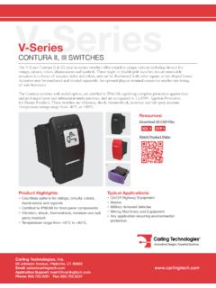
1 Sample, configure partC-SeriesHydraulic-Magnetic Circuit BreakerPRODUCT WEBPAGET ypical Applications Marine Datacom/Telecom Renewable Energy Generators & Welders Military Industrial Automation Commercial Food Medical EquipmentCompact yet robust, the C-Series hydraulic-magnetic circuit breaker is designed for high amperage and voltage applications. C-Series breakers are available as a one to six pole configuration and are rated up to 100 amps, 480 VAC/80 VDC or 240 VAC/125 VDC for UL 489 configurations. Parallel pole options offer ratings from 100-250 amps. The C-Series employs a unique arc chute design which allows for higher interrupting capacities of up to 10,000 amps. PolesVDC MaxVAC Max1-6125480 Compact Circuit Breaker with High Amperage and Voltage CapabilitiesAmps Max250 NOW PART 15% 25% 35%110010 TOLERANCE(%)OHMSCURRENT(AMPS)FIGURE - - - 100 RESISTANCE, IMPEDANCE VALUES from Line to Load Terminals(Values Based on series Trip Circuit Breaker)AMPERE RATING Time Delay Curves42, 44 & 46(50 Amps Max.)
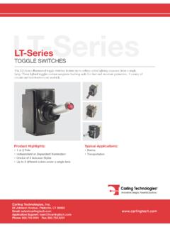
2 OfRated Delay Curves22, 24 (100 Amps Max.)26 (70 Amps Max.)Time in MillisecondstTime Delay Curves22, 24 (100 Amps Max.)26 (70 Amps Max.)60 Hz 1/2 CycleInrush Pulse Tolerance50 Hz 1/2 CycleInrush Pulse Delay Curves42, 44 & 46(50 Amps Max.)22x10xMultiple ofRated Delay Curves42, 44 & 46(50 Amps Max.) ofRated Delay Curves22, 24 (100 Amps Max.)26 (70 Amps Max.)Time in MillisecondstTime Delay Curves22, 24 (100 Amps Max.)26 (70 Amps Max.)60 Hz 1/2 CycleInrush Pulse Tolerance50 Hz 1/2 CycleInrush Pulse Delay Curves42, 44 & 46(50 Amps Max.)22x10xMultiple ofRated Tolerance CurvesTech SpecElectricalMaximum VoltageAC, 480 WYE/277 VAC, 50/60 Hz (see Table A.) UL489: AC,240 VAC. (See Table D),50/60 Hz, 125 VDCC urrent RatingsStandard current coils: , , , , , , , , , , , , , , , , , , and 100 amps. Other ratings available, see ordering Voltage CoilsDC - 6V, 12V; AC - 120V; other ratings available, see ordering Switch RatingSPDT; amps-250 VAC, DC , 65 VDC.
3 , 80 VDC,1/4 HP, 125 VAC,VDE & 125 ResistanceMinimum of 100 Megohms at 500 StrengthUL, CSA: 1960 V 50/60 Hz for oneminute between all electrically isolated terminals. C-Series Circuit Breakers comply with the 8mm spacing and 3750V 50/60 Hz dielectric requirements from hazardous voltage to operator accessible surfaces, between adjacent poles and from main circuits to auxiliary circuits per Publications EN 60950 and VDE , ImpedanceValues from Line to Load Terminal -based on series Trip Circuit ,000 ON-OFF operations @ 6 per minute; with rated current & FreeAll circuit breakers will trip on overload, even when actuator is forcibly held in the ON IndicationThe operating actuator moves positively to the OFF position when an overload causes the breaker to trip. With mid-trip, handle moves to the mid position on electrical trip of the circuit breaker. With mid trip handle with alarm switch, handle moves to the mid position and the alarm switch actuates when the circuit breaker is electrically of Poles1-6 poles 50A; 1-4 poles @ 51-70A; 1-2 poles 71-100A.
4 UL489 Handle: 1 pole 100A, 2 pole 50A; Rocker: 1 pole 100 AInternal Circuit (with or without auxiliary switch, mid trip & mid trip with alarm switch) Shunt & Relay with current or voltage trip coils, Dual Coil, Switch Only (with or without aux. switch). UL489: series (with or without auxiliary switch, mid-trip & midtrip with alarm switch). grams/pole ( oz).Standard ColorsHousing: BlackEnvironmentalDesigned and tested in accordance with requirements of specification MIL-PRF-55629 & MIL-STD-202 as follows:ShockWithstands 100Gs,6mssawtooth while carrying rated current pernMethod 213, Test Condition I . Instantaneous and ultrashort curves tested @ 90% of rated excursion from 10-55 Hz & 10 Gs 55-500 Hz, @ rated current per Method 204C, Test Cond. A. Instantaneous & ultrashort curves tested @ 90% of rated ResistanceMethod 106D, , ten 24-hourcycles @ +25 C to +65 C, 80-98% SprayMethod 101, Condition A (90-95% RH @ 5% NaCl Solution, 96 hrs).
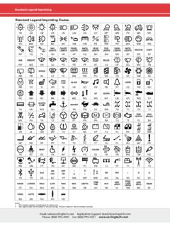
5 Thermal ShockRH @ 5% NaCl Solution, 96 hrs).Thermal Shock Method 107D, Condition A (five cycles @ -55 C to +25 C to +85 C to +25 C).Operating Temperature-40 C to +85 C*Manufacturer reserves the right to change product specification without prior (AMPS)TOLERANCE (%) - - - A: Lists UL Recognized & CSA Accepted configurations and performance capabilities as a component supplementary protectorNotes:1. Requires branch circuit backup with a UL LISTED Type K5 or RK5 fuse rated 15A minimum and no more than 4 times full load amps not to exceed 125A for 50 Amp or less rating and not to exceed 175 for 51 through 100 Amp ratingComponent Supplementary ProtectorsCircuit ConfigurationVoltageCurrent RatingShort Circuit Capacity (Amps)Application CodesConstruction NotesMax. RatingFrequencyPhaseFull Load AmpsGeneral Purpose AmpsUL / CSAULCSAWith Backup FuseWithout Backup - 100------5,000TC1, OL1, U2TC1, OL1, U2---48110 - - 70TC1, 2, OL1, U1TC1, 2, OL1, U1-71 - 100TC1, 2, OL0, U1TC1, 2, OL0, - 70---7,500TC1, 2, OL1, U1TC1, 2, OL1, U1---71 - 100TC1, 2, OL0, U1TC1, 2, OL0, - 70---10,000TC1, 2, OL1, U1TC1, 2, OL1, U1 Must have Agency "L"---71 - 100TC1, 2, OL0, U1TC1, 2, OL0, - 50---5,000TC1, 2, OL1, U1TC1, 2, OL1, U1 Must have Agency "L"125/250TC1, 2, OL1, U1TC1, 2, OL1, U1 Must have Agency "L"250TC1, 2, OL1, U1TC1, 2, OL1, U1 Must have Agency "L".
6 250 volts requires 2 pole12550 / - 1003,000TC1, OL1, U2TC1, OL1, U2 Per pole rating5,000TC1, 2, OL1, U1TC1, 2, OL1, U1 Must have Agency "L"150DC------80 - 100TC1, 2, OL0, U3---Must have Agency "L"101 - 175 Must have Agency "L" parallel pole125/25050 / - 100---3,500TC1, OL1, U2TC1, OL1, - 503,000TC1, 2, OL1, U1TC1, 2, OL1, U12 or 3 poles breaking single phase51 - 1001,000TC1, 2, OL1, U1TC1, 2, OL1, U12 or 3 poles breaking single - 1005,000TC1, 2, OL1, U2TC1, 2, OL1, U22 or 3 poles breaking single phase. Agency "L" - 503,500TC1, 2, OL1, U2TC1, 2, OL1, U2 Per pole - 1005,000TC1, 2, OL1, U1TC1, 2, OL1, U1 Must have Agency "L"51 - 705,000---TC1, 2, OL1, C1TC1, 2, OL1, - 100---3,000TC1, 2, OL0, U2TC1, 2, OL0, - 70---5,000---TC1, 2, OL1, C1TC1, 2, OL1, C13 poles breaking 3 - 90---5,000TC1, 2, OL0, U1TC1, 2, OL0, U1 Must have Agency "L" - 50---5,000--TC1, 2, OL1, C1TC1, 2, OL1, C1---480 - 30TC1, 2, OL1, C1TC1, 2, OL1, C13 poles breaking 3 phase---TC1, 2, OL0, C1TC1, 2, OL0, - 30TC1, 2, OL1, C1TC1, 2, OL1, C12 poles breaking 1 phase---TC1, 2, OL0, C1TC1, 2, OL0, C1---Dual - 50---7,500TC1, 2, OL1, U1TC1, 2, OL1, U112550 / 6013,000TC1, OL1, U2TC1, OL1, U2 Per pole rating125/2503,500TC1, OL1, U2TC1, OL1, U22 or 3 poles breaking single phase3,000TC1, 2, OL1, U1TC1, 2, OL1, U12 or 3 poles breaking single phase2503,500TC1, OL1, U2TC1, OL1, U2---33,000TC1, OL0, U2TC1, OL0.
7 U2 Per pole rating5,000---TC1, 2, OL1, C1TC1, 2, OL1, C1---2771TC1, 2, OL1, C1TC1, 2, OL1, C13 poles breaking 3 phaseShunt80DC------7,500TC1, 2, OL1, U1TC1, 2, OL1, U1---27750 / 6015,000---TC1, 2, OL1, C1TC1, 2, OL1, C12503TC1, 2, OL1, C1TC1, 2, OL1, C13 poles breaking 3 phase480 - 30TC1, 2, OL1, C1TC1, 2, OL1, C13 poles breaking 3 phase---31 - 50TC1, 2, OL0, C1TC1, 2, OL0, - 30---TC1, 2, OL1, C1TC1, 2, OL1, C12 poles breaking 1 phase---31 - 50TC1, 2, OL0, C1TC1, 2, OL0, - 50------7,500TC1, 2, OL1, U1TC1, 2, OL1, U127750 / 6015,000---TC1, 2, OL1, C1TC1, 2, OL1, C12503TC1, 2, OL1, C1TC1, 2, OL1, C13 poles breaking 3 phaseSwitch Only65DC---71 - 100---------------8071 - 100---12550 / - 100125/2502 or 3 poles breaking single phase250---3 - - 50480 - 303 poles breaking 3 phase---31 - 50---Tech B: Lists UL Recognized and CSA Accepted configurations and performance capabilities as a Manual Motor C: Lists UL Recognized, CSA Accepted, VDE and TUV Certified configurations and performance capabilities as a Component Supplementary :1.
8 Requires branch circuit backup with a UL Listed Type K5 or RK5 fuse rated 15A Minimum and no more than 4 times full load amps not to exceed 125A for 50 Amp or less rating and not to exceed 175A for 51 through 100A UL Recognized and CSA Certified at 480V refers to 3 and 4 pole versions used in a 3 , WYE connected circuit or a 2 pole version with 2 poles breaking 1 and backed up with a series fusing as stated in note 1.* Shunt and Relay Trip - Voltage Coil Construction not current coilsNotes:1 Special catalog number required. Consult :1. General Purpose ratings for UL/CSA Requires branch circuit backup with a UL LISTED Type K5 or RK5 fuse rated 15A minimum and no more than 4 times full load amps not to exceed 125A for 50 Amp or less rating and not to exceed 175 for 51 through 100 Amp D: Lists UL Listed (489), CSA Certified ( No. ) configuration and performance capabilities as a Molded Case Circuit Motor ControllersCircuit ConfigurationVoltageCurrent RatingHorsepower RatingsMax.
9 RatingFrequencyPhaseFull Load AmpsMax. HPSeries, Shunt & Relay Switch Only120 150 / - 507 1/2250 - 20335277 113480 235 Component Supplementary ProtectorsCircuit ConfigurationVoltageCurrent RatingShort Circuit Capacity (Amps)Application CodesConstruction NotesMax. RatingFrequencyPhaseFull Load AmpsGeneral Purpose Amps 1UL / CSAVDETUVWith Backup FuseWithout Backup Fuse(Inc)With Backup Fuse(Icn) Without Backup Fuse(Inc) With Backup Fuse(Icn) Without Backup FuseUL / - 70------7,500---5,0005,0001,500TC1,2,OL1 ,U1---71 - 10071 - 10010,000---5,000TC1,2,OL0,U1 Agency F, H, J or R1251 - 50---5,000---TC1,2,OL1,U1 Agency J or - 505,000TC1,2,OL1,U12P, Agency J or R50 / - 703,0001,5003,0001, - 100------5,0005,000 Agency J or - - 305,000 2---3,0001,5003,0001,500TC1,2,OL1,C1 Rocker5,0002,500 Handle, Agency F, H, J or RDual - 30---7,500---1,5005,000TC1,2,OL1,U1---25 050 / 601 & 35,0003,0003, - 707,500---5,0005,000TC1,2,OL1,U1---25050 / 601 & 35,0003,0001,5003,000TC1,2,OL1, - 305,000 2---TC1,2,OL1,C1 Rocker5,0002,500 Handle, Agency F, H, J or RUL489 Listed Branch Circuit BreakersCircuit ConfigurationVoltageCurrent RatingInterrupting Capacity (Amps)
10 Construction NotesMax. RatingFrequencyPhase Full Load AmpsWithout Backup - 10050,000 1 Limited to 2 Poles Max from 71 - 100 Amps10,000101 - 1502 Poles - Parallel Poles151 - 2503 Poles - Parallel - 1005,0001 - 3 Poles125 / - 501 or 2 Poles (2 poles required for 250 Volts)12050 / 60110,0001 - 3 Poles51 - 705,000120 / - 502 or 3 Poles (1 pole of a 3 pole unit is neutral)10,000 - 305,0001 - 2010,0002 Poles2771-2 PolesDual - 30---Tech E: Lists UL Recognized, CSA Accepted configurations and performance capabilities as Protectors, Supplementary for Marine Electrical and Fuel Systems (Guide PEQZ2, File E75596). Ignition Protected per UL 1500. UL Classified Small Craft Electrical Devices, Marine in accordance with ISO 8846 (Guide UZMK, File MQ1515) as Marine Supplementary F: Lists UL Listed configurations and performance capabilities as Circuit Breakers for use in Communications Equipment (Guide DITT, File E189195), under POLE CONSTRUCTION UL489A Listed for Communications EquipmentCircuit ConfigurationVoltageCurrent RatingInterrupting Capacity (Amps)Max.


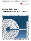
![Dimensional Specifications: in. [mm] - Carling Tech](/cache/preview/2/7/7/b/1/c/c/3/thumb-277b1cc3c1030fdd5e2f38c8b7480b64.jpg)