Transcription of CA008004EN M-Force Three-Phase Switch - …
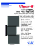
1 DescriptionEaton's Cooper Power series M-Force Switch is a distribution-class, gang-operated, factory unitized Three-Phase overhead loadbreak Switch . The M-Force Switch is offered in distribution voltage classifications of kV, 27 kV, and 38 kV. The M-Force Switch may be used for line sectionalizing, paralleling, by-passing, or stands for Magnetic force . Eaton has the only reverse loop contacts found on distribution-class sidebreak switches; a contact usually reserved for higher priced transmission switches.
2 The reverse loop contacts utilize high current magnetic forces for added reliability. The reverse loop design allows for high contact pressure to be maintained during fault conditions. This feature prevents pitting and distorting of the Switch blade and contacts even under severe momentary Three-Phase switchSwitches and DisconnectsCA008004 ENEffective January 2016 Supersedes June 2015 COOPER POWERSERIESB asic conceptCurrent-carrying conductors that are parallel to each other and have current flowing in the same direction, attract each other due to the magnetic forces acting on them (See Figure 1A).
3 Current-carrying conductors that are parallel to each other and have current flowing in the opposite direction, repel due to the magnetic forces acting on them (See Figure 1B).Current flows through the two parallel inner segments of the reverse loop contacts in the same direction, thus these two segments attract each other, initiating contact pressure. Current flow through the inner segment and the outer segment is in opposite directions, which causes a repelling force that amplifies the contact featuresReverse loop contactsThe reverse loop contacts utilize high current magnetic forces for added reliability.
4 The reverse loop contacts were adapted from Eaton's Cooper Power series KPF Line Tension Switch and have been field-proven for over 80 years. The reverse loop design allows for high contact pressure to be maintained during fault conditions. This feature prevents pitting and distorting of the Switch blade and contacts even under severe momentary overload. These contacts originally designed for high voltage transmission switches also maintain extremely cool temperatures even under the rated full load. The max temperature rise allowed per IEEE Std 1247 -2005 standard for the blade and contact area is 65 C.
5 The max temperature rise observed on the reverse loop contact area was 38 C, less than half of the allowed temperature. These types of test results, along with the proven field performance, undoubtedly make the Reverse Loop Contacts found in the M-Force Switch the premiere choice in the M-Force Switch comes standard with polymer (silicone rubber) insulators. These non-porcelain insulators offer exceptional dielectric and mechanical characteristics adding to the reliability of the M-Force Switch , while lowering the weight.
6 The M-Force Switch can be provided in cycloaliphatic epoxy and porcelain housings. Insulators come standard with " bolt circles at 15 and 25 kV. Insulators require a " bolt circle at 35 bearing assemblyThe stainless steel shaft on the rotating insulator bearing assembly has been extended to four inches. This extra length will prevent horizontal movement of the rotating insulator during operation which ensures proper blade/contact alignment which is essential for smooth operation. Another feature of the bearing assembly is the oil-impregnated bushings that provide maintenance-free operation for the life of the Switch .
7 Insulated Reliabreak armThe Reliabreak Pick-up Arm on the M-Force Switch is insulated on one side, which isolates the interrupter from the current path during a close operation. This feature allows for a wide range of adjustments between the Reliabreak arm and the blade catch finger. This increased tolerance removes the possibility of misalignment during operation which ensures proper load locking dead-end bracketsThe dead-end brackets on the M-Force Switch are of a positive locking design. This design allows for dead-ending at an angle without any distortion of the brackets.
8 This allows for a more flexible Switch that can be used in a wider variety of installation inter-phase clampsThe inter-phase control rod clamps on the M-Force Switch are designed with a jam nut through the side of the casting which locks the clamps after factory alignment. This feature eliminates any possibility of accidental slippage of the control mechanism which ensures proper operation even under icy ice shieldsThe standard M-Force Switch is capable of operating under a 3/8" ice build up. With the optional ice shields the M-Force Switch is capable of opening and closing with a 3/4" ice build up.
9 The unique shields are designed to prevent ice from building up between the contact clips as well as removing the ice from the blade during the closing operation. Per IEEE Std -1994, a chopping action is allowed during the close operation to break the ice. Due to the shearing action of the M-Force Ice Shields, the closing operation can be accomplished with one motion. No chopping is 2. Magnetic forces acting on FORCESCURRENT FLOWREPELLING FORCESREPELLING FORCESF igure 1A. Current flowing in same 1B.
10 Current flowing in opposite Data CA008004 ENEffective January 2016M- force Three-Phase 3. Illustration of M-Force NEAR BEARI NGSPI NDLE ASSEMBLYI NSULATOR ( DEFAULT)RELI ABREAKCATCHCLI P CONTACTTERMI NAL PADTERMI NAL PADPOLYMER3 Catalog Data CA008004 ENEffective January 2016M- force Three-Phase Switch dimensional dataTable 1. Dimensional (Riser) kV27 kV38 kV27 kV38 kV27 kV38 kV27 kV38 kV27 kV38 kV27 kV38 kVA79"88"119"97"108"126"79"88"97"108"119 "126"95"104"126"61"73"79"B28"33"42"28"33 "42" "40"45" "56" "30" " "27"33"36"C15"15"18"24"24"24" " " " " " "N/AN/AN/AN/AN/AN/AD29"33"52"38" " " " " "22" " "88"97"119"58"61"73"EN/AN/AN/AN/AN/AN/A2 9" "45"29" "42"93"102"124"34"34"42"FN/AN/AN/AN/AN/ "45" " " "58"N/AN/AN/AN/AN/AN/AHorizontal Pole kV27 kV38 kVA79"79"97"B36"36"45"Figure 4.