Transcription of Cablelink Plus Screed - MK Electric
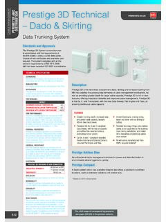
1 SCREEDED. Cablelink plus Screed FLOOR SYSTEMS. Technical Hotline +44 (0)1268 563720. Technical Cablelink plus Screed System Standards and Approvals Layout Cablelink plus Screed System range complies In order that the installation may exhibit the desired flexibility, the ducting is usually with the relevant requirements of the latest laid out on either a Grid, Fishbone or a Comb Pattern of single, double or triple runs. edition of 17th Edition of the IET Wiring A Grid Pattern is widely used in areas where the occupants require the highest Regulation (BS 7671) and to BS EN 50085.
2 Degree of flexibility in reorganising work areas. Capacity can be increased by Part 1 and BS EN 50085 Part 2-2. Additionally returning individual ring mains through different runs of duct which in itself allows the floorboxes also comply with IEC 60670. easier installation. Parts 1 and 23. The metal used complies to the requirements of BS EN 10327:2004 The Fishbone Pattern is ideal for a medium sized area where lesser boxes are required. The Comb Pattern is the most economical way of installation where least duct is FEATURE BENEFITS used. The comb pattern is suited for medium to small office areas.
3 L Tested to BS EN 50085-2-2 to accept Grid pattern 5000N load l The system incorporates numerous design features to ensure a fast and simple installation l Designed to support Cat 6 & Cat 6A structured Grid pattern cabling systems l Suitable for screeded depth from 55mm to 110mm (Height adjustment kits and floor coverings must be used). l Minimum finished floor thickness (including Grid pattern carpet, tile etc) is 74mm, with a 35mm wiring space. Can be reduced to 64mm if a 25mm wiring space can be utilised. (A CUBA-1. adjustment kit must be used) Grid pattern l Floorboxes are IP2X rated in accordance with BS EN 50085-1 Fishbone pattern l Choice of 1, 2, 3 or 4 compartment floorboxes l Self Closing lid in accordance with IEC 61534-22.
4 L Wide range of power and data accessories Fishbone pattern available to meet all requirements l PVCu ducting manufactured from 100%. recycled material*. l Quality, reliability and safety come as standard l Provision of RCD protection supports Fishbone pattern compliance to the 17th Edition of the IET Wiring Regulation (BS 7671). l 5 year guarantee Comb Fishbone pattern pattern TOP TIPS. l Distance between two junction boxes must not Comb pattern exceed 6 metres l Service Outlet Boxes fixed only on branch Header Runs Universal Junction Box ducts and not on header ducts.
5 Fixing service boxes on the header ducts affects cable Service Outlet Box Branch Runs capacity and constricts the header Vertical Access Box Comb pattern l Workstations locate over Service Outlet Boxes so that it does not interfere with normal Header Runs Universal Junction Box For a full range of corresponding products, office traffic Service see Outletin Box pages 413-424 the product selector. Branch Runs Comb pattern Vertical Access Box * based on 2014 consumption 689. Header Runs Universal Junction Box SCREEDED. Cablelink plus Screed FLOOR SYSTEMS. Technical Cablelink plus Screed System Cable Capacity Guide TABLE B METAL Screed DUCTING CABLING CAPACITY.
6 The cable factor table below is based on the 17th Edition of the SIZE COMPARTMENT CAPACITY CAPACITY. (MM) SIZE 100% (45% FILL). IET Wiring Regulation (BS 7671) and must be regarded only as 100 x 38 100 x 38 (1 comp) 3474 1563. a guideline. Care should be taken in selecting adequate trunking 112 x 25 (2 comp) 3940 1773. sections taking into consideration the number and size of cables 225 x 38 75 x 38 (3 comp) 2613 1176. involved and construction of the junction box. It is recommended 250 x 38 13 x 38 (3 comp) 2909 1309. that the initial design of trunking installations include adequate 275 x 38 91 x 38 (3 comp) 3206 1443.
7 Provision for future wiring. To determine the size of the trunking 300 x 38 100 x 38 (1 comp) 3503 1576. required, multiply the quantities of each size of conductor and appropriate factor from Table A and compare the total with the Cablelink plus Screed System ducting complies with capacity unit figure in the appropriate Table B. BS EN 50085-1:2005 and BS EN 50085-2-2:2008. The above table gives the available capacity units on 45% factor, TABLE A CABLE FACTORS applied to the internal wiring area. CABLE TYPE CSA CABLE FACTOR. POWER CABLES Carpet Cut out Dimensions 14.
8 B 14. A. 4mm PVC Stranded 6mm A. 10mm 16mm D. 25mm C. B. 86. Twin & Earth 4mm 99. The table below shows the sizes required for the carpet lid infill 6mm 148. and carpet tile cut out for the Cablelink plus Screed Floorboxes. DATA CABLES. Cat 5E UTP dia CARPET LID INFILL BOX CARPET CUT. LID LIST BASE LIST. DIMENSIONS OUT DIMENSIONS. Cat 5E STP dia 36 NUMBER NUMBER. (mm) (mm). Cat 6 UTP dia A B C D. Cat 6 STP dia 49. CXL100 152 93 CUB100 100 100. Cat 6A dia 64. CXL265 219 251 CUB265 265 265. Sample calculation CXL340 219 326 CUB340 340 340. To estimate the total number of cables that can be accommodated CUJL200 188 188 CUJ200 200 200.
9 With a 100 x 38mm ducting: CUJL265 253 253 CUJ265 265 265. Step 1 Pick the factor from Table B corresponding to CUJL240 328 328 CUJ240 340 340. 100 x 38 = 1563. DUCTING CABLE CAPACITY DATA CABLES. Step 2 Select the size of the cable that needs to be pulled through the trunking and its corresponding factor from DUCTING 60MM DUCTING 90MM DUCTING. Table A 4mm2 stranded = CAPACITY mm 1025 2300. NUMBER OF CABLES. Step 3 No. of cables = Value from (Table B / Table A) NOMINAL CABLE. 60mm DUCTING 90mm DUCTING. 1563 = 94 Cables. DIAMETER mm . @50% @75% @50% 17 25 38 57.
10 TOP TIPS 6 14 21 32 48. l 12 18 27 41. The number and location of boxes will depend on the end user requirements 7 10 15 23 35. 8 8 12 17 26. l If the furniture layout is available, a floor box should be considered for each workstation or desk l If the final furniture layout is not available as a general guide the minimum recommended distribution is one floor box for every 10m , and the maximum being one floor box per 4m . 690. SCREEDED. Cablelink plus Screed FLOOR SYSTEMS. Technical Hotline +44 (0)1268 563720. Technical Cablelink plus Screed System Cablelink plus Screed Service Box PVCu Ducting and Accessories: Materials UL94 V2 rated nylon, Pre-galvanised Manufacture Duct straight lengths are extruded from 100%.