Transcription of Calculating Creepage and Clearance Early Avoids …
1 Calculating Creepage and Clearance Early Avoids Design Problems Later Homi Ahmadi One of the most common errors uncovered by product safety engineers stems from manufacturers and designers failing to fully investigate a product's Creepage and Clearance distances. It is not unusual for manufacturers to find that a product fails the Creepage and Clearance distance test because of miscalculations or simply because the distance between two components was overlooked. Design engineers, especially printed circuit board (PCB) designers, are often not aware of the reasons for using Creepage and Clearance distances.
2 Selecting the appropriate tables in the standard and applying them properly to a design are key to avoiding problems later. Last-minute failure can also arise because design engineers do not seek input from the product safety engineers in the Early design stages. Designers sometimes assume that all safety issues relating to Creepage and Clearance have been addressed, only to discover spacing problems once the product is built. Basic Definitions Creepage Distance. Creepage is the shortest path between two conductive parts (or between a conductive part and the bounding surface of the equipment) measured along the surface of the insulation.
3 A proper and adequate Creepage distance protects against tracking, a process that produces a partially conducting path of localized deterioration on the surface of an insulating material as a result of the electric discharges on or close to an insulation surface. The degree of tracking required depends on two major factors: the comparative tracking index (CTI) of the material and the degree of pollution in the environment. Used for electrical insulating materials, the CTI provides a numerical value of the voltage that will cause failure by tracking during standard testing.
4 IEC 112 provides a fuller explanation of tracking and Tracking that damages the insulating material normally occurs because of one or more of the following reasons: Humidity in the atmosphere. Presence of contamination. Corrosive chemicals. Altitude at which equipment is to be operated. Clearance Distance. Clearance is the shortest distance between two conductive parts (or between a conductive part and the bounding surface of the equipment) measured through air. Clearance distance helps prevent dielectric breakdown between electrodes caused by the ionization of air.
5 The dielectric breakdown level is further influenced by relative humidity, temperature, and degree of pollution in the environment. When designing a switch-mode power supply for use in information technology (IT) equipment, a typical rule of thumb is to allow an 8-mm Creepage distance between primary and secondary circuits, and a 4-mm distance between primary and ground. If these dimensions are allowed for during the design stage, there is a high probability (95%) that no failure will occur with respect to Creepage or Clearance when the final product is submitted for test.
6 Working Voltages. A working voltage is the highest voltage to which the insulation under consideration is (or can be) subjected when the equipment is operating at its rated voltage under normal use conditions. The appropriate Creepage and Clearance values can be determined from the figures provided in the relevant tables in EN These values must sometimes be calculated. To use Tables I IV (2H, 2J, 2K, and 2L of the standard), the following factors must be considered: determination of working voltages, pollution degree of the environment, and the overvoltage category of the equipment's power source.
7 When measuring working voltages, it is important to measure both peak and root-mean-square (rms) voltages. The peak value is used to determine the Clearance , and the rms value is used to calculate Creepage . For example, if one measures a peak voltage of 670 V between two pins of a switching transformer in a switch-mode power supply, the Clearance distance between primary and secondary circuits must be calculated using Table I. If the unit is powered via 240 V mains and has a pollution degree of 2, the figures in the center row (marked 300 V rms sinusoidal) and center column (since the mains voltage is >150 V and < 300 V) are used to establish the required Clearance distance.
8 In this case, the value for reinforced insulation is 4 mm. One then turns to Table II (Table 2J of EN 60950), which provides additional Clearance based on the working voltages and pollution degree. (The middle column was used for Calculating this example.) The appropriate row in that column covers the actual repetitive peak insulation working voltage. In this example, the value would be mm for reinforced insulation. Adding the two figures together gives a total of mm Clearance distance. Similarly, if a voltage of 337 V rms was measured between the two pins of the switching transformer, Table IV (2L of the standard) must be used to calculate the Creepage distance between the primary and secondary circuits.
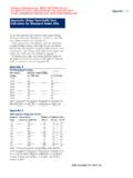
9 Assuming pollution degree 2 and material group IIIb, the required Creepage distance for basic insulation would be mm using linear interpolation. For reinforced insulation, the values for Creepage distances are double the values provided in the table for basic insulation. In this case, the required Creepage for reinforced insulation would be 7 mm. Functional, Basic, and Supplementary Insulation Pollution Degree 1 Pollution Degree 2 Pollution Degree 3 Material Group Material Group Material Group Working Voltage V Rms or Dc I, II, IIIa, or IIIb I II IIIa, or IIIb I II IIIa.
10 Or IIIb <50 100 125 150 200 250 300 400 600 800 1000 Use the Clearance from the appropriate tables Linear interpolation is permitted between the nearest two points, the calculated spacing being rounded to the next higher increment. Table IV. Table 2L of the standard provides minimum Creepage distances ( Creepage distances in millimeters). The use of these tables is explained in sections of EN 60950.