Transcription of CAMSHAFT INSTALL KA24DE INSTRUCTIONS
1 1. It is highly recommended that an oil and filter change be done before installing new cams. 2. Remove the plug wires, and valve cover from the en-gine. Use caution not to drop anything into the engine. 3. With the parking brake on, and the car out of gear (neutral), rotate the crankshaft clockwise until #1 cylin-der is at TDC (top dead center) with all of it s valve closed. To insure that this is correct, look at the crank pulley (TDC is the second mark from the left, it will usually be marked with yellow paint). Also check that the cam lobes on #1 cylinder are pointing away from the center of the motor, if they are pointing toward the center, rotate the motor one full rotation clockwise. Again check the crank pulley to see that it is on TDC. 4. Before removing the cam sprockets, the sprocket bolts must be loosened. Using a 24 (15/16ths ) wrench or socket on the bolt and a 1 open end wrench on the cam hex (in front of the front lobe), break loose but don t remove the bolts.
2 5. Carefully mark the chain links that are aligned with the dots on the gears. The dots and the marked links should be exactly the same after installing the new cams (unless JWT adjustable sprockets are used). It is impossible for the chain to jump on the lower sprocket because their isn t enough room between the sprocket and cover. 6. If the chain tensioner does not have a shoe re-tainer (early KA24DE engines), it must be locked by inserting a locking pin made from a piece of wire that fits in the pin hole on the front of the tensioner. The shoe may pop out and have to be reinserted if this is not done. 7. Remove the upper chain guide above the cam sprockets (not used on later KA24DE ). Re-move the previously loosened cam sprocket bolts and pull the sprockets away from the cams. Let the chain/sprockets lay relaxed away 1 Step 3 Step 4 Step 5 Step 7 CAMSHAFT INSTALLATION INSTRUCTIONS FOR NISSAN KA24DE ENGINES W/DOUBLE ROW CHAIN (SEE LAST PAGE FOR USING JWT CAMS IN KA24DE W/SINGLE ROW CHAIN) 9/13 UPDATE DOUBLE ROW CHAIN ONLY!
3 SEE LAST PAGE FOR USE WITH SINGLE ROW CHAIN ENGINES from the cams until ready to assemble to the new cams. Note the positions of the dowel pin on each cam, the new cams must be installed at the same positions. 8. Mark the cam bearing caps if not already marked on both the intake and exhaust sides and note that the arrows are point-ing to the front of the engine. Evenly re-move the bearing caps one turn of each bolt at a time until all are free of tension. Remove the bearing caps and place them in a clean area in the same order they are removed. Remove the old cams, caution should be taken to insure that they don t bind on the thrust surfaces of the first journal (this is also criti-cal when installing the new cams). 9. Measure the thickness of each follower shim and write it down in case you need to change it later if the clearance is not within the acceptable range. 10. Although the new cams have been fully inspected, they must be final cleaned and checked for any damage or burrs that may have occurred during shipping or handling.
4 Oil gallery plugs MUST BE in-stalled in the rear of each cam ! Apply a coating of as-sembly lube or motor oil to all journals and lobes. Care-fully lay the cams in their correct positions. Note that some JWT cams have two dowel pin holes to facilitate their use as either an intake or an exhaust cam. 2 INTEXH1ST LOBEKA24 DENOT USED NOT USED CORRECT CAM LOBE AND SPROCKET INTEXH1ST LOBEKA24 DEStep 8 Step 9 Step 10 INTAKEEXHAUSTThe intake cam is the one that has the dowel pin aligned with the #1 lobe (see diagram). 11. Reinstall all of the bearing caps. Evenly tighten 1/2 turn at a time on each bolt until all of the caps are snug ( ft-lb and again to ft-lb). Then final torque the bolts from the center bolts outward to to ft-lb. 12. Attach the sprockets to the new cams and screw the bolts in by hand. If you have positioned the cams dowels cor-rectly, only a slight rotation of the cams will be needed to engage the dowel and sprocket.
5 Check to see that the sprocket is fully seated against the cam before torquing the bolt tight. Always use a 26 or 1 wrench on the cam hex to back up your torque wrench (never use the chain for resistance)! Torque the cam sprocket bolts to 123 to 130 ft-lb. Check that your original chain marks still align with the dots on the sprockets and the lobes still point away from the center of the engine. Reinstall the upper chain rail (if used) and remove the tensioner locking wire you installed (if used). If the first lobe on either cam is pointing straight up, you probably have the cams on the wrong side of the engine! 13. Inspect your work carefully. Recheck the cam timing, the crank should be on the TDC mark, the cam sprockets and chain should look like the diagram. 14. Using a feeler gauge set, measure the shim to cam clearance of each cam lobe and write them down next to the shim thickness dimension you previously recorded.
6 If the new clearance is not between .010 inch (COLD), then a new shim is needed to cor-rect this. If the clearance is to large, use a shim that is thicker than the original shim by the amount needed to correct the clearance. See the table on page 4 for or-dering shims. JWT cams are ground to within .05 (.002 ) of the original clearance so shim changes are normally not needed, but the clearances should al-ways be checked. Shims can be changed without again removing the cams by using the special Nissan tools described in the Nissan manual. 15. Reinstall the valve cover (reapply silicone sealant at front and rear) and dis-tributor wires. Torque the valve cover bolts first to ft-lb and then to to ft-lb. 16. Break-in should consist of 10-15 minutes of 1500 2000 RPM and 50-100 miles of varied RPM below 4000 RPM. 3 Step 11 Step 14 ADDENDUM ONLY FOR KA24DE W/SINGLE ROW CHAINS IF YOUR ENGINE HAS A SINGLE ROW CHAIN, YOU MUST READ AND FOLLOW THIS SECTION!
7 ! INCLUDES 98+ ALTIMA AND 98+ frontier TRUCKS Nissan switched to a single row chain in 1998 on the Altima and frontier truck. Along with this change, they also repositioned the intake cam dowel to sit at 12 o clock to match the exhaust cam. JWT intake cams have the intake dowel posi-tioned for the double row engine (10 o clock). If you are installing JWT cams in a KA24DE with a single row chain and sprockets, you must change the position of the intake sprocket exactly as shown below. Set the exhaust cam marks exactly as the stock cam was when you removed it. Count the number of links between the exhaust mark and the new mark and link on the intake as shown below. If this is not followed exactly, you could bend the valve so double check this. If this is done correctly, the intake and exhaust lobes on the #1 cylinder will point away from the center of the engine in exactly opposite positions (like photo on page one). INTAKEEXHAUSTNEW MARK & LINKKA24DE SINGLE ROW CHAIN & SPROCKET POSITION WHEN USING AN INTAKE CAM FROM AN EARLY DOUBLE ROW CHAIN ENGINE12345678 SHIM SELECTION GUIDE 5 NOTE: Each shim series is designated for a specific KA24DE engine, but can in most cases be used in other KA24DE engines using the same 31 shim diameter.
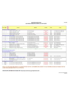
8 KAD (Japan made) (Superceded From 53 Fxx) MM KAD (Mexico made) MM KAD (USA made) 2K+ ALTIMA MM 13229-54F00 13229-F4500 13229-0Z800 13229-54F01 13229-F4501 13229-0Z801 13229-54F02 13229-F4502 13229-0Z802 13229-54F03 13229-F4503 13229-0Z803 13229-54F04 13229-F4504 13229-0Z804 13229-54F05 13229-F4505 13229-0Z805 13229-54F06 13229-F4506 13229-0Z806 13229-54F07 13229-F4507 13229-0Z807 13229-54F08 13229-F4508 13229-0Z808 13229-54F09 13229-F4509 13229-0Z809 13229-54F10 13229-F4510 13229-0Z810 13229-54F11 13229-F4511 13229-0Z811 13229-54F12 13229-F4512 13229-0Z812 13229-54F13 13229-F4513 13229-0Z813 13229-54F14 13229-F4514 13229-0Z814 13229-54F15 13229-F4515 13229-0Z815 13229-54F16 13229-F4516 13229-0Z816 13229-54F17 13229-F4517 13229-0Z817 13229-54F18 13229-F4518 13229-0Z818 13229-54F19 13229-F4519 13229-0Z819 13229-54F20 13229-F4520 13229-0Z820 13229-54F21 13229-F4521
9 13229-54F22 13229-F4522 13229-54F23 13229-F4523 13229-54F24 13229-F4524 13229-54F60 13229-F4560 13229-54F61 13229-F4561 13229-54F62 13229-F4562 13229-54F63 13229-F4563 13229-54F64 13229-F4564 13229-54F65 13229-F4565 13229-54F66 13229-F4566 13229-54F67 13229-F4567 13229-54F68 13229-F4568 13229-54F69 13229-F4569 13229-54F70 13229-F4570 13229-54F71 13229-F4571 13229-F4572 13229-F4573 13229-F4574 TO CONVERT TO INCHES MULTIPLY BY .03937