Transcription of CAMSHAFT INSTALLATION SUPPLEMENT FOR …
1 CAMSHAFT INSTALLATION SUPPLEMENT FOR nissan QR25DE 1. It is highly recommended that an oil and filter change be done before installing new cams. 2. Remove the ignition coils, valve cover and sprocket cover from the engine. Use caution not to drop anything into the en-gine. Note the O-ring between the sprocket cover and the front cover, be sure it is but back in place. 3. With the parking brake on, and the car out of gear (neutral), rotate the crankshaft clockwise until #1 cylinder is at TDC (top dead center) with all of it s valve closed. To insure that this is correct, look at the crank pulley (TDC is the first mark from the left on the pulley). Also check that the cam lobes on #1 cylinder are pointing away from the center of the mo-tor, if they are pointing toward the center, rotate the motor one full rotation clockwise.
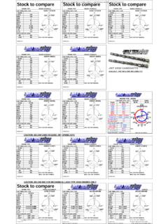
2 Again check the crank pulley to see that it is on TDC. 4. Before removing the cam sprockets, the sprocket bolts must be loosened. Using a 17 socket on the bolts and a 24 open end wrench on the cam hex (behind the front lobes), break loose, but don t remove the bolts. Never use the chain to hold the gears while breaking the bolts loose! 5. Carefully mark the chain links that are aligned with the lines on the gears. The lines and the marked links should be exactly the same after installing the new cams. It is impossible for the chain to jump on the crank sprocket because their isn t enough room between the sprocket and the lower cover. 6. The chain tensioner must be locked by inserting a locking pin (use a small drill bit or wire) on the front of the tensioner.
3 The shoe may pop out Step 3 Step 5 Step 6 NOTICE: If you do not have the proper tools and knowledge to successfully complete this INSTALLATION , have a professional nissan mechanic do it for you. This information is not complete, and is only a SUPPLEMENT to the factory nissan manual. Refer to the fac-tory manual for information not contained in this SUPPLEMENT . Break-in should consist of 10-15 minutes of 1500 2000 RPM and 50-100 miles of varied RPM below 4000 RPM CONSULT THE nissan FACTORY MANUAL BEFORE LOBEEX1ST LOBEINQR25DE CAMSHAFT DOWEL PIN LOCATIONS AT TDCNOTE THE #1 LOBE TO DOWEL RELATION. THEINTAKE CAM IS THE ONE WITH THE DOWEL CLOSESTTHE #1 LOBE AS have to be reinserted if this is not done. 7. Remove the sprockets and support the chain by hanging it over a cover bolt as shown in picture.
4 8. Mark the cam bearing caps if not already marked on both the intake and exhaust sides and mark the direction of the caps to the front of the engine. Remove the front bearing cap by first removing the bolts in the front cover and then the top bolts. Carefully pull the front bearing cap away from the head and front cover and scrap off the old seal-ant. Be certain that no old sealant falls into the engine. Evenly remove the rest of the bearing caps 1/2 turn of each bolt at a time until all are free of tension. It is critical that the cams are not cocked while loosening the bearing caps, as the cams can easily break from bending type stress (especially during installa-tion of the new cams). Remove the bearing caps and place them in a clean area in the same order they are removed from the head.
5 9. Although the new cams have been fully inspected, they must be final cleaned and checked for any dam-age or burrs that may have occurred during shipping or handling. Check that an oil gallery plug is installed in the rear of each cam! Apply a coating of assembly lube or motor oil to all journals and lobes. Carefully lay the cams in their correct positions. Note that some cams have two dowel pin holes. The intake cam is the cam that has the dowel pin closest to the #1 lobe (see diagram). The cams should be laying in exactly the same rotational position as the ones you removed (see diagram). 10. Reinstall all of the bearing caps in the marked order and direction except the front cap. Again make sure that the cams don t cock or jam in the thrust bearing (front bearing) while tightening the bolts or cam breakage can occur!
6 Evenly tighten 1/2 turn at a time on each bolt until all of the caps are snug ( ft-lb and again to ft-lb). Then final torque the bolts from the center bolts outward to to ft-lb. 2 Step 8 MARKMARKEXH. DOWELINT DOWEL#1 LOBE#1 LOBELOBE, DOWEL, AND TIMING MARK POSITIONSStep 9 Step 7 Apply silicone gasket sealant to the front cap only in ar-eas previously sealed, staying away from bearing sur-faces and oiling holes. Tighten all front cap bolts in the same steps as the other caps. the sprockets to the chain and align the sprocket timing marks to the marks you made on the chain. Attach the sprockets to the new cams and screw the bolts in by hand. If you have positioned the cams correctly, only a slight rotation of the cams will be needed to engage the dowels and sprockets.
7 Check to see that the sprockets are fully seated against the cams before torquing the bolt tight. Always use a 24 or 15/16 wrench on the cam hex to back up your torque wrench (never use the chain for resistance)! Torque the cam sprocket bolts to 94 to 115 ft-lb. Check that your original chain marks still align with the marks on the sprockets and the lobes still point away from the center of the engine. Remove the tensioner locking wire you in-stalled. Inspect your work carefully. Recheck the cam timing, the crank pulley should be on the TDC mark and the cam lobes, sprockets and chain should look like the dia-gram in step 9. 12. Using a feeler gauge set, measure the follower to cam (lash) clearance of each cam lobe. Cold valve lash should be between .010 inch (.254.)
8 33 mm). The new cams are ground to within .002 (.05 ) of the original cams base circle so follower changes are normally not needed, but the clear-ances should always be checked. If the lash clearances are not correct, you will need to remove the cam(s) and change the followers as needed before continuing. Note the metric thickness number on the underside of the follower(s) and order the corrective thicker or thinner follower(s) from your nissan dealer as needed. 13. Reinstall the cam sprocket cover using silicone sealant and reconnect the cam phaser electrical plug. Be sure the O-ring is installed between the covers during assembly. Torque the 6 cam sprocket cover bolts to 9-10 ft-lb. the valve cover (reapply silicone sealant at point were originally applied) and ignition coils.
9 Torque the valve cover bolts first to ft-lb and then to ft-lb. Finish reinstalling all other parts in reverse order and inspect your work carefully be-fore starting the engine. 15. Break-in consists of 15-20 minutes at 1800 2000 RPM immediately after initial startup and 50-100 miles of varied RPM driving below 4000 RPM. 3 Step 12 Step 11 212 MILLAR AVE. EL CAJON, CA 92020 619 442-0680