Transcription of Camshaft Torque Analysis of Diesel Engine - Inpressco
1 International Journal of Current Engineering and Technology E-ISSN 2277 4106, P-ISSN 2347 5161 2017 Inpressco , All Rights Reserved Available at Research Article 59| MITCOE, &DIAT, Pune,AMET-2017, IJCET INPRESSOS pecial Issue-7 (March 2017) Camshaft Torque Analysis of Diesel Engine Swapnil S Hatwalane* and Basavraj Kothavale Department of Mechanical Engineering, Faculty at MITCOE, Savitribai Phule Pune University, Pune (INDIA) Accepted 12 March 2017, Available online 16 March 2017, Special Issue-7 (March 2017) Abstract Drive Torque requirement for Engine valve train system is the Analysis of Torque required to drive the valve train by the crankshaft. There are different types of valve trains used such as overhead Camshaft , pushrod valvetrain and end pivot valvetrain system. There are different types of followers used for these valvetrain like flat face, roller or oscillating follower.
2 The Torque required for each of these valve train is different according to its application. Hence finding Torque requirement for each valve train and the factors influencing it is the main aim of the project. The analytical Torque values compared with the software simulations and also the actual testing of the test rig. Keywords: Engine valve train system etc. 1. Introduction 1 Engine Valve train system is one of the most important system of an Engine . The improper design would lead to the complete failure of Engine and high power losses. Hence a correct operation and design is of utmost importance. Valve train consists of many parts like camshafts, valves, valve springs, HLA (Hydraulic Lash Adjuster), Pushrods, Rocker arms and Tappets or Followers. This adds to a large inertia of total components driven by the Camshaft .
3 Currently the valve train system must be optimized to improve its performance and reduce its weight. Camshafts are an important part of a valve train system. These camshafts are driven by crankshaft and they run at about half the angular speed of crankshaft. In high speed engines the rotational speeds of Camshaft can be very high leading to high torsional vibrations. These torsional vibrations give rise to high stresses in the valve train. Fatigue Analysis of Camshaft is very much important as it is expected to run for longer durations without affecting its strength. The need of this project of Drive Torque requirement for Engine valve train system by using different types of followers is detailed in the following sections. The valve train system is a significant part of the power train function & contributes to a power loss detrimental to fuel economy.
4 Poor valve train dynamics characteristics & abnormal valve train vibrations significantly affect the performance, durability & noise of an Engine . The challenges for valve train designer *Corresponding author: Swapnil S Hatwalane are that the system must operate robustly with changing with changing operating conditions 2. Need of Work Power requirement for the Engine to drive the valvetrain. Partial Engine optimization. Dynamic Analysis . Camshaft Bearings and gear selection and optimization. Tribological significance. Tallying the analytical and the actual Torque with the software simulated Torque . 3. Literature survey The Torque variations of Camshaft thus have a considerable effect on the working of crankshaft and Engine flywheel.
5 In this competitive automotive market engines with high power output consuming less fuel is very important. [Paper 1] Optimization of Engine is thus important in every phase of Engine development. Torque acting on the Camshaft depends on the inertia forces of components, spring forces, vibratory forces and the frictional forces. Hence the Torque Analysis helps in optimizing the complete valve train inertia by choosing different materials etc. The largest source of vibration next to crankshaft is the valve train. The Camshaft Torque can give an indication of the possible inherent torsional vibrations. Camshaft Torque Analysis has a great influence on the valve train dynamics. It can be used to know the dynamic behavior of the flexible components such as valve springs. The difference Swapnil S Hatwalane et al Camshaft Torque Analysis of Diesel Engine 60| MITCOE, &DIAT, Pune,AMET-2017, IJCET INPRESSOS pecial Issue-7 (March 2017) between the calculated and the analytical Torque can indicate the friction present in the valve train and hence we can reduce it.
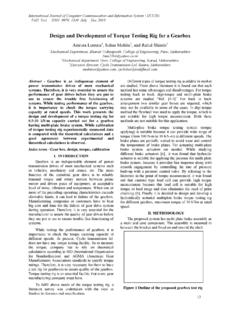
6 To enable optimization of the valve train system and component design it is necessary to be able to predict the various contributions to the valve train friction at the design stage itself. Hence the Camshaft Torque has a great influence on the tribological factors as well .By finding friction Torque we can change the oils, oil film thickness, friction in bearings, effects of oil, additives etc. Thus the effect on valve train friction by many variations in valve train design (changes in the cam profile, spring design, surface finish, tappet coating etc.) can be evaluated. [Paper 3] Inputs for pushrod mechanism by using flat face follower for 3 cylinders (inlet valve): Valve Mass 166gm Mass of Retainer 31gm Mass of Valve Spring 65gm Rocker arm Cam width 24mm Follower Radius Follower Width 9mm Stiffness of Spring 23N/mm Valve lift 12mm Cam lift Rocker ratio Total weight at cam Total weight at valve Wire diameter 3mm Spring free length Density of steel 7850kg/m3 Moment of inertia 10-4kg/m2 mass of guide 36gm mass of follower 188gm mass of cam 75gm Mass at Valve Side( Mass of Valve, Spring, Retainer, Guide) 304gm Mass at Cam Side( Mass of Follower, Cam) 258gm Comparison of Analytical and Software.
7 (a) Camshaft Torque for flat face pushrod mechanism of 3 cylinder inlet valve Engine Analytical Graph Software Graph Inputs for pushrod mechanism by using flat face follower for 3 cylinders (exhaust valve): Valve Mass 163gm Mass of Retainer 31gm Mass of Valve Spring 65gm Rocker arm Cam width 24mm Follower Radius Follower Width 9mm Stiffness of Spring 23N/mm Valve lift 12mm Cam lift Rocker ratio Total weight at cam Total weight at valve Wire diameter 3mm Spring free length Density of steel 7850kg/m3 Moment of inertia 10-4kg/m2 mass of guide 36gm mass of follower 188gm mass of cam 75gm Mass at Valve Side( Mass of Valve, Spring, Retainer, Guide) 304gm Mass at Cam Side( Mass of Follower, Cam) 258gm Comparison of Analytical and Software: (a) Camshaft Torque for flat face pushrod mechanism of 3 cylinder inlet valve Engine .
8 Analytical Graph Swapnil S Hatwalane et al Camshaft Torque Analysis of Diesel Engine 61| MITCOE, &DIAT, Pune,AMET-2017, IJCET INPRESSOS pecial Issue-7 (March 2017) Software Graph Inputs required for type 2 (input) Valve Mass 48gm Mass of Retainer 7gm Mass of Valve Spring Rocker arm Cam width 12mm Follower Radius Follower Width 9mm Stiffness of Spring Valve lift Cam lift Rocker ratio Total weight at cam Total weight at valve Wire diameter 3mm Spring free length Density of steel 7850kg/m3 Moment of inertia 10-4kg/m2 Spring Force mass of guide 55 mass of follower 51 mass of cam 75 Mass at Valve Side( Mass of Valve, Spring, Retainer, Guide) Mass at Cam Side( Mass of Follower, Cam) Dddd1 126gm Inputs required for type2 (exhaust) Valve Mass Mass of Retainer Mass of Valve Spring Rocker arm Cam width 12mm Follower Radius Follower Width 9mm Stiffness of Spring Valve lift Cam lift Rocker ratio Total weight at cam Total weight at valve Wire diameter 3mm Spring free length Density of steel 7850kg/m3 Moment of inertia 10-4kg/m2 Spring Force mass of guide 36gm mass of follower 50gm mass of cam 75gm Mass at Valve Side( Mass of Valve, Spring, Retainer, Guide) Mass at Cam Side( Mass of Follower, Cam) 125gm Remark From the above graphs it can be concluded that the Torque required for exhaust valve is greater than that of inlet.
9 Reasons: 1. The cam lift of exhaust valve is more 2. The weight of the exhaust valve is more hence more drive Torque is required to operate it 5. Experimental Analysis Development of test rig Component Required Camshafts, springs, Exhaust Valve, Inlet Valve, Hydraulic Lash Adjusters, Flanges, Hydraulic Motor, Drive Motor, Engine Head, Hydraulic Valves, Pressure Gauge, Sump, Ball Valves, Pipes and Tubes, Nipples, Bolts and Nuts, Pressure Reducing Valve and Flow Control Valve, Plugs, keys, VFD Connection. Development Process: 1) Design of test setup. Swapnil S Hatwalane et al Camshaft Torque Analysis of Diesel Engine 62| MITCOE, &DIAT, Pune,AMET-2017, IJCET INPRESSOS pecial Issue-7 (March 2017) 2) Collection of parts like springs, valves, HLAs, Nuts and Bolts for Engine Assembly.
10 3) Tapping of Camshaft . 4) Assembly of Engine head. 5) Manufacturing of flanges and plates. 6) Mounting of Engine head on plates. 7) Manufacturing of sump. 8) Connection of drive motor with Engine head. 9) Lubrication system. 10) Connection of hydraulic motor through pipes & tubes with Engine head and Sump. 11) Pressure gauge and connection of different types of valves like ball valve, Pressure reducing valve etc. 12) Completion of the assembly. 13) VFD connection to run the setup. Experimental methods for Camshaft Torque measurement 1 Torque measurement by electric drive motor: The intake Camshaft can be driven by an electric motor connected to the end of the Camshaft operates 12 intake valves via hydraulic tappets. The drive Torque is measured by the electric motor. Voltage and current measurement gives the Camshaft Torque . 2 Torque measurement by strain gauging: Transducers require some electrical input power or excitation.