Transcription of CAPACITOR AND APFC SYSTEM SERVICE MANUAL …
1 INSTALLATION & TROUBLE SHOOTINGCAPACITOR AND APFC SYSTEMSERVICE MANUALSAFE & SUREL&T check if required kVAr of capacitors are the type of CAPACITOR installed is suitable for application or the capacitors are if the capacitors are permanently ON . The CAPACITOR are not switched off when the load is not working, under such condition the average power factor is found to be lower Check whether all the capacitors are operated in APFC depending upon the load Check whether the APFC installed in the installation is working or not. Check the CT connection is taken from the main incomer side of transformer, after the fix compensation of transformer. Refer Fig. if the load demand in the SYSTEM is Check if power transformer compensation is POWER FACTOR IS NOT IMPROVINGC alculation of required CAPACITOR required should be calculated taking the data from electrical bill copies of last 4-6 months if bill is not available please take initial power factor as note that the max demand given in electrical bill is in kVA not in kW.
2 Power factor = kWH / kVAH (these data are generally provided in electricity bills)Initial Power factor -(Before installation of CAPACITOR )Recorded demand -516kVA (Highest recorded demand)Req power factor (To be decided by customer)kW = kVA x Power Factor= 516 x = 387 Required CAPACITOR = kW x Multiplying Factor= ( x 516) x Multiplying Factor =387 x = 215kVAr LoadLoadSupplyBusTRCTC ableTransformerCompensationACBCRSDFF11-M 1-M F2K1-MC1-MAPFC PanelH1F21-MF1C1-M1-MKSDFCR CTTRP ower transformerCurrent transformerPower factor controllerSwitch disconnector fuseContactorsCapacitor stop fusesControl fusesCapacitor stopsLoad63 SAFE & SUREL&T SWITCHGEARESP SERVICE MANUAL64 SAFE & SUREL&T SWITCHGEARESP SERVICE MANUALM ultiplying factor for calculating kVArKVAr REQUIRED FOR TRANSFORMER OF KVAr
3
4
5 1 Target PFKVA required for compensation5% of kVA of kVA of kVA rating of the transformerUpto and including 315 kVA315kVA - 1000 kVAAbove 1000 kVA65 SAFE & SUREL&T SWITCHGEARESP SERVICE MANUALT humb Rule if HP is compensation for motor should be calculated taking the details from the rating plate of motor Or the CAPACITOR should be rated for 1/3 of HP.
6 Refer Fig,No 2 for the connection of CAPACITOR . Where to connect compensation should be provided to take care of power transformer. Power and distribution transformers, which works on the principle of electro-magnetic induction, consume reactive power for their own needs even when its secondary is not connected to any load. The power factor will be very low under such situation. To improve the power factor it is required to connect a fixed CAPACITOR or CAPACITOR bank at the LT side of the transformer. For approximate kVAr of capacitors required Refer Table the installation is having various small loads with the mixture of large loads then the APFC should be recommended. Note that APFC should have minimum step rating of 10% as smaller loads are small then the CAPACITOR should be connected parallel to load.
7 The connection should be such that whenever the loads are switched on the CAPACITOR also switches on along with the load. Refer Fig that APFC panel can maintain the power factor on side of transformer and it is necessary to provide fix compensation for Power transformer Refer Fig case there is no transformer in the installation, then the for sensing power factor should be provided at the incoming of main switch of the plant. Refer Fig No-3 Fig. Ensure the CAPACITOR is protected using fuse / The CAPACITOR is switched ON along with starter3. In case of star-delta starter the CAPACITOR should switch ON on delta CompensationSupply BusTransformerCircuit BreakerMMMMFig. F2K1-MC1-MH1F21-MF1C1-M1-MKSDFCR CTCurrent transformerPower factor controllerSwitch disconnector fuseContactorsCapacitor stop fusesControl fusesCapacitor stopsLoad66 SAFE & SUREL&T SWITCHGEARESP SERVICE MANUALS election of CapacitorFollowing industries are presently installed with MPP-H processing processing units industries.
8 Industries are presently installed with MD-XL rolling plants3. Sugar plants4. Govt research institutes5. Plastic moulding units6. Defence units7. Airports8. of from above capacitors MPP-S are generally used in various industries having pure steady inductive loads. Do not use in the industries having harmonic generating loads such as welding, drives, ups, rectifiers, :The industries like cement, sugar, software industries and steel plants need data of harmonics for designing suitable compensation recommendation for heavy industries should be given in consultation with L&T / MEHER Engineers as the harmonic generating loads are found to be increasing in all the industries 67 SAFE & SUREL&T SWITCHGEARESP SERVICE MANUAL2.
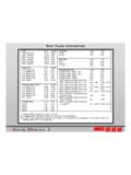
9 TESTING OF capacitors AT SITEM easurement of VoltageCheck the voltage using tongtester at CAPACITOR terminals. Ensure that the tong tester / multimeter used is of True RMS type . Please note that the current output ot 440 volt CAPACITOR connected to a SYSTEM of 415 volt will be lesser than rated value. Table no - & gives you the resultant kVAr output of the CAPACITOR due to variation in supply voltage. Refer formula no 1. Caution:Please ensure customer is not comparing wrong technologies such as our MPP-S capacitors with other makes APP/MD/ or heavy duty MPP CAPACITOR . Please also ensure that the customer is comparing with similiar voltage rated CAPACITOR . TABLE phase 440V 10 15 13,34 20 25 205,52 TABLE phase 415V capacitance across two terminals with third terminal open.
10 (Micro farad) 440V kVAr 440V Line current 440V kVAr at 415 VLine Current at 415V Measured capacitance across two terminals with third terminal open. (Micro farad) 415V kVAr 415V Line current 415V kVAr at 440 VLine Current at 415V 8,43 69,31 10 11,24 14,75 18,44 115,51 15 16,86 20 22,48 25 28,10 & SUREL&T SWITCHGEARESP SERVICE MANUALM easurement of CurrentDischarge of CapacitorMeasurement of Capac