Transcription of Carbon Monoxide (CO) Gas Detection and Control …
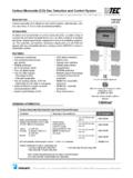
1 Specifications subject to change without notice. | USA 140924 | Page 1 of 612700 Stowe Drive, Suite 100, Poway, CA 92064 | Ph: (858) & (888) | Monoxide (CO) Gas Detection and Control SystemDESCRIPTIONC arbon Monoxide (CO) Detection and Control system, wall-mounted, with one, two, three or four remote detect and Control levels of Carbon Monoxide (CO) in a wide variety of commercial and industrial applications such as vehicle exhaust in parking structures, engine repair shops, equipment rooms and ventilation systems, etc. The controller can interface via binary outputs and up to (2) 4-20 mA signals with any compatible electronic analog Control , DDC/PLC Control or automation Continuous monitoring CO electrochemical sensor, gas specific Polarity protected Up to (4) sensor inputs Four (4) digital inputs Five (5) relay outputs.
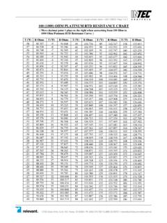
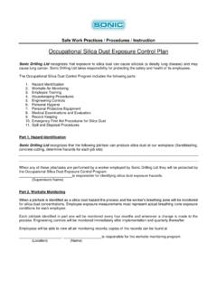
2 - Five-stage Control - Fail-safe assignable Two (2) analog outputs, 4-20 mA - Selectable for low, high or averaging Optional BACnet coupler upwards communication to BAS Liquid Crystal Display (LCD)PolyGardLGC-CO LED status indicators Built-in horn Keypad user interface Simple menu-driven programming RFI/EMI protected Modular plug-in technology Overload & short-circuit protected NEMA 4X, transmitter enclosure NEMA 4X, controller enclosure Easy maintenanceORDERING INFORMATIONU pwards Communication OptionsBACnetNRTL Performance Tested & Certified Conforms to STDUL 2075 / UL 2017 City of Los Angeles ApprovedCarbon Monoxide (CO) Detection and Control System PackageControllerSensor(s) / Transmitter(s)Part NumbersDigital programmable menu-driven keypad user interface LCD & LEDs,24 VDC, NEMA 4X enclosureInputs: (4) 4-20 mAOutputs: (5) Relays, SPDT, 8 A (2) 4-20 mABuilt-in (1) HornSensor range:0-250 ppm CO,4-20 mA, 2-wire,loop powered 24 VDC,NEMA 4X wall mount enclosureIncl.
3 (1) CO remote sensorLGC-CO-01 Incl. (2) CO remote sensorsLGC-CO-02 Incl. (3) CO remote sensorsLGC-CO-03 Incl. (4) CO remote sensorsLGC-CO-04 BACnet upwards communication coupler T5-BAC-1-A (external)T5-BAC-1-AFactory configured CO alarm levels/setpoints: Low alarm @ 25 ppm (relay #01) Horn alarm @ 100 ppm (relay #05) High alarm @ 100 ppm (relay #02) Other setpoints/programming are available on special request. All devices are field programmable and subject to change without notice. | USA 140924 | Page 2 of 612700 Stowe Drive, Suite 100, Poway, CA 92064 | Ph: (858) & (888) | each stage level (S1-S5) Assignable to any relay- sensor fail-safe Assignable to any stage levelTime delay switching Selectable for make and brake of each sensor point (SP1 to SP4) 0-9,999 secondsAnalog output Two (2) independent 4-20 mA signal, 500 max.
4 Load, selectable as low, high or averaging of sensor inputsAudible alarm 85 db (10 ft), enabled or disabled, selectable; assignable to stage level S1, S2, S3, S4 or S5 Alarm acknowledgment Menu-driven and system reset function for latched relaysUser InterfaceKeypad type Refer to section User Interface & Controller Touch buttons Six (6)Status LED s Red: Alarm Yellow: Fault (fail)Digital display Liquid Crystal Display (LCD), two lines, 16 characters per line, 1 digit resolution, backlit- unit display Menu selectable, per sensor; ppm, %LEL, Vol%, F, %RH, %, ppk, CBACnet Interface,optional* Read status information via BACnet coupler and BACnet- Profile, BACnet-Services and BACnet BIBBsCoupler module C5-BAC-98 (B)Communication TCP/IP 10/100 Mbits/secConnector Ethernet RJ45 Interface BACnet-ProfileDescription BACnet-Services Who-is (execute) I-am (initiate) ReadProperty WriteProperty Object types Version , Permissible ambientcontroller- working temperature 23 F to 104 F (-5 C to 40 C)
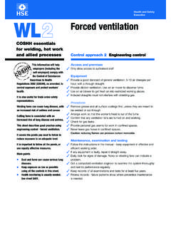
5 - storage temperature 23 F to 86 F (-5 C to 30 C)- humidity 15 to 95% RH, non-condensingPermissible ambientsensor/transmitter- working temperature 14 F to 122 F (-10 C to 50 C)- intermitted temperature -4 F to 122 F (-20 C to 50 C)- storage temperature 41 F to 86 F (5 C to 30 C)- humidity, continuous 15 to 90% RH, non-condensing- humidity, intermitted 0 to 99% RH, non-condensing- working pressure Atmospheric 10%SPECIFICATIONSE lectricPower supply- controller 24 VDC, -15%/+20%, 50/60 Hz, auto-resettable fuse- sensor(s)/transmitter(s) 24 VDC from controller, loop powered, polarity protectedPower consumption 13 VA ( A), w/max sensor connectionsRF/EMI protected W @ 3 ft.
6 (1 m) radiatedSensor PerformanceGas detected Carbon Monoxide (CO)Sensor element Electrochemical, diffusionRange Span field adjustable from 0-200 to 0-300 ppm via calibration, 0-250 ppm factory setResolution ppm of readingRepeatability of readingLong term output drift < signal loss/monthResponse time t90 < 50 element life expectancy 3-5 years, normal operating environmentSensor coverage 5,000 , max. 10,000 (465 m2, max. 930 m2), under ideal conditions Installation LocationSensor mounting height 5 to 6 ft. ( to m) above floorType of ControlGeneral Five-stage (S1 to S5) Control , assignable up to five (5) binary/ relay output, Low-med-high-fault/fail-horn*, or low1-low2-med1-med2-high, or any other combinations (* = horn/audible alarm built-in and factory pre-configured to relay output R05 )Analog inputs Four (4) 4-20 mA, for remote sensorsAnalog reading Current and mean (average) valueStage level / setpoint Field adjustable over full range, five (5)
7 Per analog input, assignable to current or mean (average) value- hysteresis/ switching differential Selectable for each sensor pointDigital inputs Four (4), each can be individually assigned to any relay ( ). - application Remote audio/visual alarm reset or override functionRelay outputs (R1-R5)w/ status LEDs Five (5) SPDT, 8 A 24 VAC/VDC-250 VAC contact resistance 100 m , max.(*) BACnet Interface: NRTL Certification to UL STD 61010-1 Pending Specifications subject to change without notice. | USA 140924 | Page 3 of 612700 Stowe Drive, Suite 100, Poway, CA 92064 | Ph: (858) & (888) | ,ControllerEnclosure (panel)- material Polycarbonate, impact resistance EN 50102/IK08, flammability rating UL 94-5V- conformity UL Type 1, UL 508/UL 50 standards- color Light gray, smoked gray for cover- protection NEMA 4X (IP65)- installation Wall (surface) mountedDimensions (H x W x D)- base x x in.
8 (200 x 190 x 105 mm)Cable entry 5 holes for 1/2 in. conduit, coveredWire connection Terminal blocks, Push-on connect and screw type for lead wireWire size- input Min. 22 AWG ( mm2) Max. 16 AWG ( mm2)- output Min. 24 AWG ( mm2) Max. 14 AWG ( mm2)Weight lbs ( kg)Enclosure (panel) approval UL Listed, E75645 Physical,Sensor/TransmitterEnclosure, standard- material Polycarbonate, UL 94-HB, fire-retardant- conformity UL 50- color Light gray- protection NEMA 4X (IP65)- installation Wall (surface) mounted, or single gang electrical boxDimensions (H x W x D) x x in. (130 x 84 x 75 mm)Cable entry 1 hole for 1/2 in. conduit for wall (surface) mounting and 1 hole on back side of base plate for single gang electrical box mountingWire connection Terminal blocks, screw type for lead wireWire size Min.
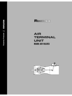
9 24 AWG ( mm ), Max. 14 AWG ( mm )Wire distance Max. loop resistance 500 (= wire resistance plus controller input resistance)Weight lbs ( kg)Enclosure approval UL Listed, E208470 CSA Certified, E208470 Approvals / ListingsSystem NRTL Perf. Tested & Certified:- sensor/transmitter Conforms to ANSI/STD UL 2075- controller Conforms to ANSI/STD UL 2017- transmitter & controller City of Los Angeles CE VDI 2053, air treatment systems for garages and tunnels EMC-Compliance 89/336/EWG, LVD 73/23/EWGW arranty Two years material and workmanship, 12 months normal exposure for sensor elementSpecifications subject to change without notice. | USA 140924 | Page 4 of 612700 Stowe Drive, Suite 100, Poway, CA 92064 | Ph: (858) & (888) | INTERFACE & CONTROLLERK eypad User InterfaceSystem OperationAll programming is made via the keypad user interface in combination with the display screen.
10 Security is provided via two password levels. The lower level password (1234) allows to override or to reset system status functions. The upper level password (9001) allows all programming and override Page DisplayAfter powered on, displays INTEC and Date/Time and changes to sensor reading display unless a system error occurs; then the error is displayed. Main MenuDisplays headings of System Errors , Stage Status Relay Status , Sensor Readings , Relay Setup , SP (Sensor Point) Setup , Data Logger and System Setup .Sub Menu System Errors Displays errors, reset corrected errors, and historical error Menu Stage Status Displays status of each SP sensor point, stage level/setpoint exceeded. Sub Menu Relay Status Displays status and manual Control of each output Menu Sensor Readings The current or average values are displayed for each SP sensor point with sensing type and engineering unit (ppm, %LEL, Vol%, F, %RH, %, ppk, C).