Transcription of CARPENTRY TRAINING MANUAL (SPECIALISED CARPENTRY)
1 CARPENTRYTRAINING MANUAL (SPECIALISED CARPENTRY ) This compilation has been created by This compilation has been created by eBay ID is crossOur eBay ID is cross--thethe--abyssabyssPlease visit our current eBay auctionsPlease visit our current eBay auctionsBy clicking By clicking herehereWe offer discounts for multiple orders We offer discounts for multiple orders and fixed rate global shippingand fixed rate global shippingCARPENTRY TABLE OF CONTENTS Page ,,,..,.,,..,..~i Chapter 1. Construction Drawings .. , .. *.. , .. l-l Architectural symbols , Line Conventions, and Material Conventions .. l-l WorkingDrawings .. 1-2 SitePlans .. 1-3 Elevations .. 1-4 Floor Plans .. 1-4 Detail Drawings .. 1-7 Sections .. 1-7 Details .. l-10 Wood Framing Drawings .. l-10 Light Wood Framing .. 1-12 Heavy Wood Framing .. 1-17 Chapter 2. Construction Planning and Materials .. , .. , .. , 2-1 Planning .. 2-1 Built-in-PlaceMethod .. 2-1 Panel Method .. 2-2 Materials.
2 2-3 .. 2-3 Hardware .. 2-5 Chapter 3. Bills of Materials.. 3-l Materials Takeoff List .. 3-1 Materials Estimate List.. 3-2 Bill of Materials Format .. 3-4 DISTRIBUTION RESTRICTION: Approved for public release; distribution is unlimited. *This publication supersedes FM 5-551, 23 February 1984. i Page Chapter 4. Building Layout and Foundation .. , .. , .. , .. , . , , 4-1 Layout .. 4-1 Laying Out a Rectangular Building Site .. 4-2 Laying Out an Irregular Building Site.. 4-2 Setting Batter Boards .. 4-2 Extending Lines .. 4-3 Squaring Lines .. 4-5 .. 4-5 Wall Foundations .. 4-5 Column or Post Foundations .. 4-6 Chapter 5. Forms for Concrete .. , .. , .. , .. , , .. , , .. , .. , , .. , .. , .. , . , .. , 5-l Form 1 Form Construction .. 5-l Foundation and Footing Forms .. 5-2 3 Column Forms .. 5-6 Beam and Girder Forms .. 5-6 Floor .. 5-6 Stair Forms .. 5-7 Form Removal .. 5-7 , Chapter 6. Rough ,..,.,..,..6-1 Types of Framing .. 6-l 1 Heavy Framing.
3 6-3 3 ..6- 4 ~6- 4 6 Sills .. 6-7 Platform Construction .. 6-7 Balloon-Framed Construction.. 6-8 Braced-Framing Sills.. 6-8 Built-Up Sills .. 6-8 Girders ..6- 8 Size Requirements .. 6-9 Load Area .. 6-10 Floor Load .. 6-11 Built-Up Girders .. 6-12 3 Girder Supports .. 6-14 Girder 5 / ii FM 5-426 page 5 5 Floor Joists for Platform Construction.. 6-18 Floor Bridging .. 6-18 Floor Openings .. 6-19 0 Finish Floors .. 6-20 Walls and 2 Corner Posts .. 6-23 Partition Posts .. 6-25 Studs .. 6-26 Girts ..6-2 6 Ibp Plate and Sole Plate.. 6-26 Bridging .. 6-28 Plumbed Posts and Straightened Walls .. 6-28 9 Exterior .. 6-31 5 Wall .. 6-36 Stovepipes .. 6-36 Ventilators ..6-3 7 Stairways .. 6-38 Stairway Framing .. 6-38 Risers and Treads .. 6-40 Chapter 7. Roof Systems and Coverings .. 7-1 ~..7- 1 ..7- 2 Rafters .. 7-2 Trusses ..7- 8 4 Roof ..7-15 Roof Coverings .. 7-15 Asphalt and Asbestos-Cement Roofing .. 7-15 Built-Up Roofing Material.
4 7-18 Reroofing .. 7-19 Asphalt-Shingle Roofs .. 7-19 Asphalt-Prepared Roll Roofings .. 7-21 Built-Up Roofs .. 7-22 Slate Roofs .. 7-25 Tile Roofs .. 7-25 Asbestos-Cement Roofs .. 7-26 Metal Roofs .. 7-26 Wood-Shingle Roofs .. 7-26 .. Ill Page / Chapter 8. Doors and Windows .. , .. , .. , .. , , . 8-l Doors .. 8-l Types of Doors .. 8-l Door Frames .. 8-3 6 Door ..8- 6 Door 6 Lock Installation .. 8-9 Windows .. 8-9 0 Window Sashes .. 8-11 ..8-12 Window Screens .. 8-12 Door Screens .. 8-12 Hoods or Canopies .. 8-13 Chapter 9. Finish CARPENTRY .. 9-1 Interior Wall and Partition Coverings .. 9-1 Plywood and Fiberboard .. 9-1 ..9- 1 7 / ..9- 9 Sheetrock .. 9-9 9 Fiberboard .. 9-9 ~..9-1 0 Chapter 10. Nonstandard Fixed .. , .. , , .. , .. , , .. , .. , . , .. , .. , . , .. , 10-l Bridge Classification .. 10-l Substructure .. 10-2 Abutments .. 10-2 Intermediate Supports .. 10-2 5 Construction Procedures .. 10-5 9 9 Flooring .. lo-10 0 0 1 End 1 iv FM 5-426 Page Chapter 11.
5 Timber-Pile Wharves.. , , .. , .. , , .. , . , .. , , , .. , .. 11-l Types of Wharves .. 11-l ~pesofPiles .. 11-l BearingPiles .. 11-1 Fender Piles .. 11-l MooringPiles .. 11-2 Installation of Piles .. 11-2 Using Special Tools.. 11-2 StraighteningPiles .. 11-3 Cutting Piles .. 11-4 Capping Timber Piles.. 11-4 Bracing Piles .. 11-4 Wharf Superstructure .. 11-6 Stringers .. 11-6 7 Stringpieces .. 11-7 Fender Piles and Chocks.. 11-7 Pile Clusters and Corner Fenders.. 11-8 Floating Log Fenders (Camels) .. 11-9 Pile-Mooring Dolphins .. 11-9 Docking Hardware .. 11-10 Hardware Installation .. 11-11 Anchorages for Hardware .. 11-11 Appendix A. Conversion Tables .. A-l Length .. A-l Area .. A-l Linear Measure .. A-l Appendix B. CARPENTRY Abbreviations and symbols , , .. , . , , .. , .. , , .. , , .. B-l Abbreviations .. B-l symbols .. B-3 Architectural .. B-3 Plumbing Electrical Appendix C. Appendix D.. B-4 .. B-5 Manpower Estimates .. C-l General Information.
6 D-l Floor and Wall Tile .. D-l Resilient Floor Tile .. D-l Ceramic and Other Specialty Tiles.. D-2 Suspendedceilings .. D-3 V FM 5-426 Page AcousticalTile .. D-3 Grid-System Components .. D-3 Installation .. D-3 Painting Ceilings and Walls .. D-4 Ceilings .. D-4 Walls .. D-4 Cleanup .. D-5 Glossary-l References-l .,..,..,..,..,.,..,..,., Index-l vi Before the carpenter can begin his work, he must have a complete set of construction drawings orprints. He must be familiar with how the drawings are prepared. He should also know how to readthe drawings so that he will understand what he must do to comply with their requirements. Thischapter will help the carpenter to reach that understandingARCHITECTURAL symbols . LINE CONVENTIONS, AND MATERIAL CONVENTIONSThe plan for a building must give all the details necessary toconstruct the building. Therefore, it usually consists of acollection of sheets, called a set of plans. Each sheet shows thedetails of a different phase or part of the construction.
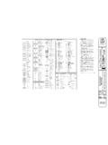
7 Several ofthe sheets will be devoted to floor plans. Other sheets in the setwill show construction details (such as wiring, plumbing, andair-conditioning details and types and quantities of materials).Refer to Appendix A for conversion symbols on construction drawings show the typeand location of windows (Figure 1-1), doors (Figure 1-2), andother features. They show the general shape of an actualarchitectural feature and show any motion that is supposed 1-2. Door symbolsFigure 1-1. Window symbolsLine conventions are differenttypes and weights of linesused to represent thefeatures of an object. Themeaning of a line withcertain characteristics hasbeen standardized and willbe the same on any line conventions mustbe understood in order toread drawings. The lineconventions most oftenencountered in constructionprints are shown anddescribed in Figure conventions aresymbols that show the type ofmaterial used in thestructure. The symbolselected normally representsthe material in some way; forexample, the symbol for woodshows the grain in the wood.
8 (However, it is not alwayspossible to use a commoncharacteristic of the materialfor the symbol.) (Appendix Bgives the symbols for themost common types ofmaterials.)Figure 1-4, page 1-4, showstypical exterior and interiorwall symbols . (Note how thematerial conventions areused in the makeup of thesymbols for masonry, brick,and concrete walls.)The carpenter should knowall of the symbols formaterials to help him read a construction drawing. A symbol on a drawing should always bechecked if there is any doubt about its meaning. Refer to Appendix B for common abbreviationsand DRAWINGSW orking drawings and specifications are the main sources of information for supervisors andtechnicians responsible for the actual construction. The construction working drawing gives acomplete graphic description of the structure to be erected and the construction method to set of working drawingsincludes both general anddetail drawings. Generaldrawings consist of plans andelevations; detail drawingsconsist of sections and PLANSA site plan (also called a plotplan) shows Property lines andlocations.
9 Contours and profiles. Building lines. Locations of structures tobe built. Existing structures. Approaches. Finished grades. Existing and new utilities(such as sewer, water, andgas).Figure 1-5, page 1-5, shows atypical site plan. Appropriateoutlines show the location ofeach building. The new facilitycan be located by referring tothe schedule of facilities onthe plan. The site plan has anorth-pointing arrow toindicate site north notmagnetic north. Each facilityhas a number (or code letter)to identify it in the schedule offacilities. The contour linesshow the elevation of the earthsurfaces. (All points on a contour have the same elevation.)Distances are given between principal details and reference lines. (The coordinate reference lineson the figure are centerlines of the roads surrounding the area.) All distances in a plan viewsimply give the horizontal measurement between two points; they do not show terrainirregularities. (The sizes of proposed facilities are given in the schedule of facilities.)
10 Examine the site plan shown in Figure 1-5 to see what information can be obtained from it. Forexample, the contour lines show that the ground surface of the site area slopes. The location andidentification of each facility are given. Most of the facilities are spaced at least 60 feet apart, butthe library (facility No. 3) and the recreation building (facility No. 4) are only 15 feet apart. Thelibrary is the smallest of the four buildings and is closest to the road- the east wall of the library is20 feet from the centerline of the road, while the other buildings are 30 or 60 feet from are drawings thatshow the front, rear, or sideview of a building orstructure. Sample elevationviews are given in Figure 1-6,page 1-6. Constructionmaterials may be shown onthe elevation. The groundlevel (called the grade)surrounding the structuremay also be shown. Whenmore than one view is shownon a drawing sheet, eachview is given a title. If anyview has a scale differentfrom that shown in the titleblock, the scale is givenbeneath the title of that centerline symbol ofalternate long and shortdashes shows finished floorlines The hidden line symbolof short, evenly spaceddashes shows foundationsbelow the grade that Figure 1-6 showsthe footings are below show the locations and types of doors and windows.