Transcription of Cascade Tub Installation Manual 360745 Rev F - 02-04-08
1 Aqua-Aire Sit-Bath System 6900 Standard / Bariatric / End OpeningInstallation / Assembly Instructions PENNER PATIENT CARE, INC Box 523 / 102 Grant St. Aurora, NE 68818 360745 Revision F 02/04/08 1-866-PENNERS 1-866-736-6377 1-800-732-0717 E-mail Address: Web Site: Cascade End Opening TUBS- 360010-1, 360010-1L, 360010-1W, 360010-X, 360010-XL, and 360010-XW, 361910-1, 361910-X, 362010-1, 362010-1L, 362010-X, 362010-XL, RESERVOIRS- 370000-1W, 370000-1WL, 370000-XW, 370000-XWL 2 2 Table of Contents TABLE OF CONTENTS ..2 INTRODUCTION: ..3 TERMINOLOGY AND SYMBOLS MEANINGS:..3 BASIC ROOM DIMENSIONS: ..3 DRAIN REQUIREMENTS: ..6 HOT AND COLD WATER SUPPLY REQUIREMENTS:..7 ELECTRICAL REQUIREMENTS.
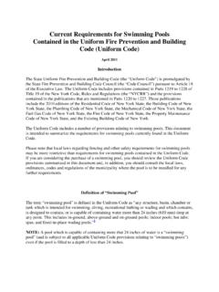
2 7 UNPACKING THE TUB: ..8 UNPACKING THE RESERVOIR: ..8 TUB MODIFICATIONS FOR RESERVOIR: ..8 ASSEMBLING THE RESERVOIR: ..9 WATER SUPPLY HOSE CONNECTIONS:..9 ANCHORING THE TUB/RESERVOIR: ..9 WATER SUPPLY AND DRAIN CONNECTIONS: ..10 ELECTRICAL CONNECTIONS: ..10 FINISHING UP:..11 TUB AND RESERVOIR CONTROLS: ..12 3 3 Figure 1 Room layout for Standard Cascade without Reservoir Introduction: These instructions are for the Installation of a Cascade Sit-Bath System 6900 Tub, Standard or Bariatric, with or without a Cascade Reservoir. The Reservoir is an optional accessory, which is to be pre-filled prior to placing the resident into the tub. Then the water in the reservoir can be released into the tub. This shortens the time required before the tub is full and the whirlpool can be started. Terminology and Symbols Meanings: When the terms left or right are used with reference to the tub, this means left or right as you look at the control panel from the seat end of the tub.
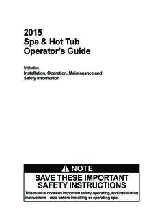
3 Meaning: Safety warning. Failure to understand and obey this warning may result in injury to you or to others. Meaning: Failure to follow these instructions may cause damage to parts or systems. Note: Refer to the Tub Controls section of this Manual for the location of any of the controls referenced. Basic Room Dimensions: Figure 1 shows a room layout for a Standard Cascade tub without a reservoir. Figure 2 shows a room layout for a Standard Cascade with a Standard Reservoir. Figure 3 shows a Room layout for Standard Cascade with a Wide Reservoir. Figure 4 shows a Room layout for Bariatric Cascade with a Wide Reservoir. Figure 5 shows Room layout for Cascade with Reservoir side view. Figure 6 shows Room layout for End Opening Cascade with Reservoir side view. CAUTION 4 4\ Figure 2 Room layout for Standard Cascade with Standard Reservoir Figure 3 Room layout for Standard Cascade with a Wide Reservoir 5 5 Figure 4 Room layout for Bariatric or Wide Cascade with a Wide Reservoir Figure 5 Room layout Side View for Cascade with Wide Reservoir 6 6 Figure 7 Room Layout Top View for End Opening Cascade Figure 6 Room Layout Side View for End Opening Cascade 7 7 Drain requirements: The tub is equipped with a 2 nominal (2 3/8 ) PVC drain pipe.
4 As shown in Figure 8, the tub s drain pipe is approximately 11 from the wall and 5 1/4 above the floor. Figure 8 shows two different options for roughing in the drain pipe from the floor or from the wall. It is recommended that a licensed plumber make all plumbing connections. He can select the best method of connection for the particular situation. Hot and cold water supply requirements: 3/4 supply lines with on/off valves with 3/4 NPT female threads. We recommend 3/4 ball valve with 3/4 NPT female ports. (Valves supplied by others.) See figure 8 for recommended locations. For optimum performance, dynamic pressures should be nominally equal between hot and cold supplies. Maximum static supply pressure: 145 PSI. Maximum dynamic/maintained supply pressure: 81 PSI. Maximum supply Hot water temperature: Consult local requirements for maximum allowed supply temperatures. (Not recommended over 120oF) Electrical requirements: The Cascade tub Aqua-Air (with reservoir) is rated amps at 120 Volts AC.
5 A 15 amp GFCI circuit is required. (The optional Cascade reservoir, is rated at .75 amp and is connected to the tub s electrical box via hard wiring.) 8 8 Unpacking the tub: 1. Remove the tub from the shipping crate. 2. Locate and save the Installation parts. 3. Remove all access doors and place them where they will not be damaged during the Installation process. 4. If a Cascade Reservoir is to be installed with the tub, continue with Unpacking the Reservoir . If not, skip to Water Supply Hose Connections . Unpacking the Reservoir: 1. Remove the Reservoir from the shipping crate. 2. Locate and save the Installation parts. 3. Remove all access doors and place them where they will not be damaged during the Installation process. Tub Modifications for Reservoir: Cascade tubs are manufactured and packed for Installation without a reservoir. To install it with a reservoir, a couple of modifications are required.
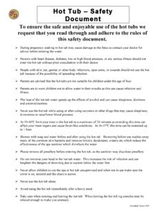
6 1. Remove the wall trim from the end of the tub. This is the off white colored trim that is pressed onto the edge of the fiberglass that would go against the wall. Replace it with the blue trim that is packed with the reservoir. The off white trim can be discarded. 2. Remove the black hole plug located just above the overflow escutcheon by removing the plastic nut. This plug and nut can be discarded 3. Replace the plug with the reservoir outlet fitting, Gasket, and outlet adapter. (These are packed with the reservoir) See figure 9 for assembly order. Ensure that the opening of the outlet fitting is pointed directly down after final tightening. 4. Unscrew and remove the cap from the water line port that points out the back of the tub. This will be the connecting point for the reservoir supply hose. Figure 9 Reservoir Outlet Assembly 9 9 Assembling the Reservoir: 1. Locate the Reservoir at the back end of the Cascade tub and use the provided hardware (3/8 x 3 3/4 bolts, flat washers, and hex nuts) to affix the reservoir to the frame of the tub s frame through the holes provided.
7 Ensure that the reservoir is centered with the tub. Snug up the hex nuts, but do not over-tighten the nuts. 2. Connect the reservoir outlet pipe to the outlet adapter with the provided flex coupling and tighten. Reference Figure 9. 3. Connect the reservoir supply hose, from the reservoir plumbing assembly, to the water line port at the back of the tub. 4. Connect the overflow tee to the drain of the tub. Water Supply Hose Connections: 1. Locate one of the provided connecting hoses (packed with the tub) and connect the male thread end to the hot water supply ball valve. 2. Connect the male threaded end of the other provided connecting hose to the cold water supply ball valve. Anchoring the Tub/Reservoir: Note: These instructions for anchoring the tub are written with the assumption that the Installation is being done on a concrete floor. If this is not the case, the tub can be anchored with simple lag screws (not provided).
8 There are two anchoring holes for anchoring the tub. 1. Place the tub/reservoir in the final Installation position. The reservoir should be against the wall. 2. Locate and mark (on the floor) the location of the tub anchoring points. (two 3/8 diameter holes in the return flange located inside the large access doors on the tub) If installing a tub with reservoir, there are also two anchoring points for the reservoir. These are located in the return flanges just inside the access doors of the reservoir. 3. Remove the tub and drill a 5/16 diameter x 1 1/2 inches deep hole in the floor at the marked locations. A masonry drill will be required. 4. Clean the drilled holes and clean the drilling dust from the area. 5. Place the tub/reservoir back into position, over the anchoring holes. 6. Insert the provided anchors through the flange and into the anchor holes just drilled. 7. Tighten the nuts until the anchor locks the tub in position.
9 10 10 Water Supply and Drain Connections: Note: It is highly recommended that a licensed plumber make the connections of the hot and cold water supply and the connection to the drain. 1. Connect the ends of the connecting hoses (hot and cold water supply) to the respective ports on the tub. Ensure that there are sealing gaskets within the swivel fittings on the hoses. 2. Connect the drain (waste) of the tub to the facility s drain system. 3. The system needs to be checked for any leaks in the entire system. However, the electrical connections must be made prior to doing this. Once the electrical connections have been made, continue with step 4. 4. Open the facility s supply valves to the tub and check for leaks. If no leaks are found, check the entire plumbing system for any leaks. Look for leaks while each of the following systems are running: Tub fill , Shower , and Disinfecting.
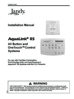
10 Electrical Connections: Warning: This unit is to be connected only by a licensed electrician. A minimum of 15 amp 120 volt service is required with ground fault circuit interrupter. 1. Remove the covers from the electrical box of the tub (and reservoir). 2. For tubs with reservoirs, connect the reservoir electrical supply lead to the tub s electrical kit. a. Remove the hole-plug from the left side of the tub electrical box. b. Run the cable lead through that hole and secure using the cord restraint and nut provided. c. Connect the line wire to the line distribution bar located in the upper right corner of the tub s electrical box. It will have only black wires connected to it. See figure 10. d. Then connect the neutral and ground wires, neutral, and ground terminals respectively. These are labeled accordingly. e. Replace the cover of the reservoir s electrical box. 3. Run flexible conduit and the proper size wires, from the facility s junction box to the Fig.