Transcription of Cast Steel Float & Thermostatic Steam Trap FT450
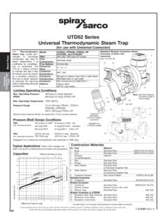
1 Steam TrapsFloat &Thermostatic518 Steam TrapsFloat &ThermostaticThe product must not be used in this product must not be used in this regionas damage to internals may (psig)Pressure bar gTemperature CTemperature F400300200100075257239221232014510435290 46458072520304032500 Steam saturation curveThermostatic Air Vent Operating RangeModel FT 450 (Replaces FT 32) PMO 465 psig (see below) Sizes 3/4" to 2" Connections NPT Carbon Steel Body Construction Stainless Steel Internals Options ANSI 150, 300 or 600 RF flanged SW Connections to ANSI Bimetal Air Vent on , 10, 14, 21 and 32 Drain plug tapped 1/2" NPT models for superheat Steel Float & Thermostatic Steam TrapFT450 The trap contains a Float valve mechanism which modulates to discharge condensate continuously at Steam temperature, while non-condensible gases are released by a separate internal balanced pressure Thermostatic air vent.
2 Construction Materials No. part Material 1 Body cast Steel ASTM A216 WCB 2 Cover Bolts Alloy Steel ASTM A 193 B7 Cover Nuts 3/4" & 1" 7/16 - 14 UNC-2A ASTM A 194 2H 1-1/2" & 2" 5/8-11 UNC-2A 3 Cover Gasket Exfoliated Graphite 4 Cover cast Steel ASTM A216 WCB 5 Valve Seat (3/4" & 1") Stainless Steel Main Valve Assembly Stainless Steel w/ erosion deflector (1-1/2" & 2") 6 Valve Seat Gasket Stainless Steel (3/4" & 1") Main Valve Assy Stainless Steel Reinforced Exfoliated Graphite Gasket 1-1/2" & 2" 7 Pivot Frame Assy Stainless Steel Set Screws ( 3/4" & 1") 10-24 Fillister Head Main Valve Assembly Stainless Steel Cap Screws (1-1/2") 1/4-20 Studs & Nuts (2")
3 5/16-18 8 Ball Float & Lever Stainless Steel 9 Air Vent Assembly Standard Stainless Steel 9A Optional Bimetal Corrosion resistant Bimetal and Stainless Steel 10 Air Vent Seat Gasket Stainless Steel 11 Support Frame Stainless Steel 12 Pivot Frame Stainless Steel 13 Erosion Deflector Stainless Steel Local regulation may restrict the use of this product below the conditions quoted. Limiting conditions refer to standard connections the interests of development and improvement of the product, we reserve the right to change the " & 1"1-1/2" & 2"28761345813923126 51 Capacities: See TIS Limiting Operating Conditions* Max. Operating Pressure : 65 psig ( barg) (PMO) FT450 -10: 145 psig (10 barg) FT450 -14: 200 psig (14 barg) FT450 -21: 300 psig (21 barg) FT450 -32: 465 psig (32 barg)Max.
4 Operating Temperature Bimetal optional air vent See graph for Thermostatic 750 F (400 C) at operating air vent pressures below 505 psig Pressure Shell Design Conditions For NPT, SW, ANSI300, ANSI600* PMA 535 psig/650 F 37 barg/342 C Max. allowable pressure 505 psig/750 F 35 barg/400 CTMA 750 F/0-505 psig 400 C/0-34 bargMax. allowable temperature* The limiting operating and design conditions for ANSI 150 flanged units will be limited by the Flange ApplicationsAll process equipment, particularly when controlled by modulat-ing temperature control valves; unit heaters, air heating coils, heat exchangers and Steam main drip TrapsFloat &Thermostatic519 Steam TrapsFloat &ThermostaticCast Steel Float & Thermostatic Steam TrapFT450 MaintenanceThis product can be maintained without disturbing the piping connections.
5 Complete isolation from both supply and return line is required before any servicing is performed. The trap should be disassembled periodically for inspection and cleaning of the valve head and seat, operating mechanism and air vent. Worn or damaged parts should be replaced using a complete valve mechanism assembly and/or air vent installation and maintenance instructions are given in IMI , which accom-panies the SpecificationSteam traps shall be of the mechanical ball Float type having Steel bodies, horizontal line connections, and stainless Steel valve heads, seats and ball floats. Incorporated into the trap body shall be a stainless Steel balanced pressure Thermostatic air vent capable of withstanding 45 F(25 C) of superheat and resisting waterhammer without sustaining damage.
6 Internals of the trap shall be completely servicable without disturbing the pipeline strainer should be installed ahead of any Steam trap. Full port isolating valves should be placed to permit servicing. The trap should be installed below the drainage point of the equipment with a collecting leg before the trap, in a position so that the Float arm is in a horizontal plane and the Float rises and falls vertically, with the flow direction as indicated on the body. Refer to IMI for complete erosion deflector is pressed into the body during manufacture and not available as a PartsValve Mechanism Kit w/ Float ( 3/4" & 1") A,B,C,D,E,F,GValve Mech. Kit (1-1/2" & 2") A,B,D,PAir Vent Kit(PMO up to 21 bar) H,J,L,M,NAir Vent Kit (PMO 32 bar) H,KGasket Kit (3 of each) B,K,TBall Float (1-1/2"& 2") CAEDCFBADCKKHTUGNJMHLBAir Vent Assembly3/4" & 1" Main Valve Assembly1-1/2" & 2"Main Valve Assembly Bimetal Air Vent Assembly special optional Spirax Sarco, Inc.
7 2017 Spirax Sarco, Inc., 1150 Northpoint Blvd, Blythewood, SC 29016 Telephone: (803) 714-2000 FAX (803) 714-2222P - 2" Inlet BaffleP1-1/2"Inlet BaffleGHwithdrawal*ANSI 600 " 419 mmDimensions (nominal) in inches and millimetersSize-DNAA1 BCDEFGHNPT/SWFlg kg1 kg1 kg2 *406* kg
