Transcription of Catalogue HY30-8249/UK Hydraulic motor/pump General ...
1 4 Parker HannifinPump and motor DivisionTrollh ttan, SwedenHydraulic motor /pumpSeries F11/F12 Catalogue HY30-8249/UKF11 cross section 1. Barrel housing 2. Valve plate 3. Cylinder barrel 4. Guide spacer with O-rings 5. Timing gear 6. Roller bearing 7. Bearing housing 8. Shaft seal 9. Output/input shaft 10. Piston with laminated piston ring 10 1 2 3 4 5 6 7 8 9F11 and F12 are bent axis, fixed displacement heavy-duty motor /pump series . They can be used in numerous applications in both open and closed loop 3 ERIES & IS AVAILABLE IN THE FOLLOWING FRAME SIZES and versions: - F11-5, -6, -10, -12, -14 and -19 with CETOP mounting flange and shaft end - F11-10, -12 and -14 with ISO flange and shaft - F11-10, -12, -14 and -19 with SAE flange and shafts 3 ERIES & CONFORMS TO CURRENT )3/ AND 3!
2 % MOUNTING flange and shaft end configurations. A very compact cartridge version is also 4 HANKS TO THE UNIQUE SPHERICAL PISTON DESIGN & & motors can be used at unusually high shaft speeds. Operating pressures to 480 bar provides for the high output power capability. s 4HE ANGLE BETWEEN SHAFT AND CYLINDER BARREL ALLOWS for a very compact, lightweight 4HE LAMINATED PISTON RING OFFERS IMPORTANT ADVANTAGES such as low internal leakage and thermal shock 4HE PUMP VERSION HAS HIGHLY ENGINEERED VALVE PLATES for increased selfpriming speed and low noise, avail-able with left and right hand 4HE & & MOTORS PRODUCE VERY HIGH TORQUE AT START up as well as at low /UR UNIQUE TIMING GEAR DESIGN SYNCHRONIZES SHAFT AND cylinder barrel, making the F11/F12 very tolerant to high 'G' forces and torsional (EAVY DUTY ROLLER BEARINGS PERMIT SUBSTANTIAL EXTERNAL axial and radial shaft 4HE & gS AND & gS HAVE A SIMPLE AND STRAIGHT FOR-ward design with very few moving parts.)
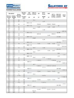
3 Making them very reliable 4HE UNIQUE PISTON LOCKING TIMING GEAR AND BEARING set-up as well as the limited number of parts add up to a very robust design with long service life and, above all, proven reliability. General information5 Parker HannifinPump and motor DivisionTrollh ttan, SwedenHydraulic motor /pumpSeries F11/F12 Catalogue HY30-8249/UK1234567891231045678911F12 cross sections 1. Barrel housing 2. Valve plate 3. Cylinder barrel 4. Piston with piston ringF12-30, -40, -60, -80 and -90(F12-60 shown) 5. Timing gear 6. Tapered roller bearings 7. Bearing housing 8. Shaft seal 9. Output/input shaft 10. Port E (F12-110 and -125) 11. Needle bearings (F12-110 and -125)F12-110 and -125(F12-110 shown)Legend: General information6 Parker HannifinPump and motor DivisionTrollh ttan, SwedenHydraulic motor /pumpSeries F11/F12 Catalogue HY30-8249/UK Frame size F11 -5 -6 -10 -12 -14 -19 Displacement [cm3/rev] Operating pressure max intermittent1) [bar] 420 420 max continuous [bar] 350 350 motor operating speed [rpm] max intermittent1) 14 000 11 200 11 200 10 300 9 900 8 900 max continuous 12 800 10 200 10 200 9 400 9 000 8 100 min continuous 50 50 Max pump selfpriming speed2) L or R function.
4 Max [rpm] 4 600 4 200 3 900 3 900 3 500 motor input flow max intermittent1) [l/min] 69 67 110 129 142 169 max continuous [l/min] 63 61 100 118 129 154 Main circuit ), max [ C] 80 80 min [ C] -40 -40 Theoretical torque at 100 bar [Nm] Mass moment of inertia (x10-3) [kg m2] Weight [kg] 11 Frame size F12 -30 -40 -60 -80 -90 -110 -125 -150 -250 Displacement [cm3/rev] 150 242 Operating pressure max intermittent1) [bar] 480 480 420 480 480 420 420 max continuous [bar] 420 420 350 420 420 350 350 motor operating speed [rpm] max intermittent1) 7 300 6 700 5 800 5 300 5 000 4 800 4 600 3 500 3 000 max continuous 6 700 6 100 5 300 4 800 4 600 4 400 4 200 3 200 2 700 min continuous 50 50 Max pump selfpriming speed2) L or R function; max [rpm] 3150 2870 2500 2300 2 250 2200 2 100 1 700 1 500 motor input flow max intermittent1) [l/min] 219 268 347 426 465 528 575 525 726 max continuous [l/min] 201 244 317 386 428 484 525 480 653 Main circuit ), max [ C] 80 80 min [ C] -40 -40 Theoretical torque at 100 bar [Nm] Mass moment of inertia (x10-3) [kg m2] 5 40 46 Weight [kg] 12 21 26 26 36 36 70 77 1) Intermittent: max 6 seconds in any one minute.
5 2) Selfpriming speed valid at sea level. 3) See also installation information, operating HannifinPump and motor DivisionTrollh ttan, SwedenHydraulic motor /pumpSeries F11/F12 Catalogue HY30-8249/UKOrdering codesF12-ISOF rame sizeCode Displacem. (cm3/rev) 030 040 060 080 090 110 125 size 30 40 60 80 90 110 125 Code Option P Prepared for speed sensor (x) (x) (x) (x) (x) (x) (x)Frame size 30 40 60 80 90 110 125 Code Main ports F SAE 6000 psi flange x x x x x x xFrame size 30 40 60 80 90 110 125 Code Shaft seal N NBR1), low pressure (x) (x) (x) (x) (x) (x) (x) V FPM2), high temperature, x x x x x x x high pressureFrame size 30 40 60 80 90 110 125 Code Shaft D DIN spline Optional (x) (x) (x) (x) (x) (x) (x) Z " " Optional (x) (x) (x) (x) (x) (x) (x) K Metric key Standard x x x x x x x P " " Optional (x)
6 - - - - - -Frame size 30 40 60 80 90 110 125 Code Option L01 Integr. flushing valve (x) (x) (x) (x) (x) -3) -3) MVR Make-up valve clockwise rotation (x) - - - - - - MVL Make-up valve counter clockwise rotation (x) - - - - - -Frame size 30 40 60 80 90 110 125 Code Mounting flange I ISO flange x x x x x x xFrame size 30 40 60 80 90 110 125 Code Function M motor x x x x x x x Pump: L counter clockw. (x) (x) (x) (x) (x) (x) (x) R clockwise (x) (x) (x) (x) (x) (x) (x) x : Available (x): Optional : Not available1) NBR - Nitrile rubber2) FPM - Fluor rubber3) F12-110 and -125: Accessory valve block (page 45)Version number (assigned for special versions)F12 FrameSIZEF unctionMainportsMountingflangeShaftsealS haftVersionnumberOptionpage 43-44 Optionpage 5130 Parker HannifinPump and motor DivisionTrollh ttan, SwedenHydraulic motor /pumpSeries F11/F12 Catalogue HY30-8249/UKA1A1A3B3K3L3C3A2G2J2N2G3H3J3 F3R2Q2S22)D3 E3 (Tol.
7 K6)P2L2M2D2 E2 F2 (tol. h8)H2( 0,5)K2B2C2 D1 (x4)B1C1T3 Type I mounting flange (ISO 3019/2)Port E (third drain port)F12-110 and -125 barrel housing(ISO /cartridge version)Port BPort APort DType K (P)Key shaft2) Type Z has no threadType D (Z) spline shaftPort C1)F12-80 shownSpeed sensor (optional)Type I flangeSee table1) Inspection/ drain portFlushing valve(optional)F12-30, -40, -60, -80, -90, -110 and -125(ISO versions)Installation dimensions31 Parker HannifinPump and motor DivisionTrollh ttan, SwedenHydraulic motor /pumpSeries F11/F12 Catalogue HY30-8249/UK Dim. F12-30 F12-40 F12-60 F12-80 F12-110 F12-90 F12-125 A1 B1 118 146 146 158 180 C1 118 142 144 155 180 D1 11 18 A2 100 110 125 135 145 B2 59 65 70 78 85 C2 25 26 22 32 38 D2 8 8 10 12 14 E2 33 42 42 52 58 F2 100 125 125 140 160 G2 172 173 190 216 231 H2 J21) 50 60 60 70 82 J22) 50 - - - - K2 55 52 54 L2 40 50 50 56 70 M2 5 5 5 7 6 N2 137 154 179 P2 8 8 8 8 8 Q2 28 28 33 36 41 R23) 35 35 40 45 50 R24) 43 35 35 41 - S23) M12 M12 M12 M16 M16 x24 x24 x28 x36 x36 S24 )
8 - M12 - M12 - x24 x28 A3 122 134 144 155 170 B3 66 66 66 75 83 C3 D3 M12 M12 M12 M16 M16 E3 30 30 35 40 45 F3 33 33 38 43 49 G3 137 154 179 H3 J3 24 24 28 36 36 K3 L3 18 20 20 20 22 T3 - - - - 68 1) Key shaft type K 4) Spline shaft type Z 2) Key shaft type P 5) Special number 264 3) Spline shaft type D Spline shaft (DIN 5480) = Max 350 bar operating pressureKey shaft Type K (std) Type P (opt.) Type X (opt.) F12-30 30 25 - -40 30 - 355) -60 35 - - -80 40 - - -90 40 - - -110 45 - - -125 45 - - Type D (standard) Type Z (optional) F12-30 W30x2x14x9g -40 W32x2x14x9g W30x2x14x9g -60 W35x2x16x9g W32x2x14x9g -80 W40x2x18x9g W35x2x16x9g -90 W40x2x18x9g W35x2x16x9g -110 W45x2x21x9g W40x2x18x9g -125 W45x2x21x9g W40x2x18x9g Ports F12-30 F12-40 F12-60 F12-80 F12-110 F12-90 F12-125 A, B 3/4" 3/4" 3/4" 1" 11/4" SIZE Screw M10 M10 M10 M12 M14 thread1) x20 x20 x20 x20 x26 C M22 M22 M22 M22 M22 thread2) D M18 M18 M22 M22 M22 thread2) E - - - - M22 thread , B.
9 ISO 6162 1) Metric thread x depth in mm 2) Metric thread x pitch in dimensions51 Parker HannifinPump and motor DivisionTrollh ttan, SwedenHydraulic motor /pumpSeries F11/F12 Catalogue HY30-8249/UK Speed sensorA speed sensor kit is available for series F11/F12. A ferrostat differential (Hall-effect) sensor installs in a separate, threaded hole in the F11/F12 bearing housing .On F12 the speed sensor is directed towards the ring gear. On F11 the speed sensor is directed towards the pistons. The sensor output is a 2 phase shifted square WAVE SIGNAL WITHIN A FREQUENCY RANGE OF (Z TO K(Z NOTE: - The motor bearing housing must be prepared for the speed pick-up; refer to the F11/F12 ordering codes (pages 7-12). - On F11 the pistons position must be known before mounting. - Additional information is provided in the Instruction ( Catalogue HY30-8301/UK).
10 - The speed sensor is also shown in the illustrations on pages 19, 20, 23, 24, 26, 27, 30, 32, 34 and 36 Part number for Speed sensor is 378 sensorF12 with speed with speed sensor52 Parker HannifinPump and motor DivisionTrollh ttan, SwedenHydraulic motor /pumpSeries F11/F12 Catalogue HY30-8249/UKSeries F12 &RAME SIZE 3 PEED ;RPM= L MIN= F12-30 3500 4 8 F12-40 3000 5 10 F12-60 3000 7 14 F12-80 2500 8 16 F12-90 2500 8 16 F12-110 2300 9 18 F12-125 2300 9 18 F12-150 2200 10-20 F12-250 1800 12-22 series F11 &RAME SIZE 3 PEED ;RPM= L MIN= F11-5 5500 1-2 F11-6 4500 2-3 F11-10 4500 2-3 F11-12 4500 2-3 F11-14 4500 2-3 F11-19 4000 2-4 Clockwise rotationPort APort BCounter clockwiserotationDirection of rotationThe M and H versions of series F11, and the M version of series F12, are L and R pump versions are uni-directional, allowing higher selfpriming speeds (refer to page 16).