Transcription of CATIA Part Design Fundamentals - GWNU
1 1 Part Design Fundamentals 2 Objectives of the course In this course you will learn basic methods to create and modify solids features and parts Targeted audience New CATIA V5 Users Prerequisites CATIA Basics Course Presentation 1 day 3 Table of Contents (1/2) to CATIA V5 Part Design Workbench Presentation Features Creating Pads Pad: Reverse Side Creating Pockets Creating Thin Solids Creating Shafts Limiting Features Creating Holes Features Creating Drafts Variable Draft Angle Filleting Edge Fillet with Limiting Planes, Faces or Surfaces 4 Table of Contents (2/2) Edge Fillet: Trim Ribbon Face-Face Fillets Tri-Tangent Fillets Variable Radius Fillets Chamfering Drafted Filleted Pads/Pockets Shelling a Part Creating Patterns Mirror Parts Modifying Profile Geometry Reordering Features Modifying Features 5 introduction to Part Design You will become familiar with the CATIA V5 Part Design main features 6 What is Part Design ?
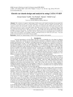
2 The Version 5 Part Design application makes it possible to Design precise 3D mechanical parts with an intuitive and flexible user interface, from sketching in an assembly context to iterative detailed Design . Version 5 Part Design application will enable you to accommodate Design requirements for parts of various complexities, from simple to advanced. This new application, which combines the power of feature-based Design with the flexibility of a Boolean approach, offers a highly productive and intuitive Design environment with multiple Design methodologies, such as post- Design and local 3D parameterization. As a scalable product, Part Design can be used in cooperation with other current or future companion products such as Assembly Design and Generative Drafting. The widest application portfolio in the industry is also accessible through interoperability with CATIA Solutions Version 4 to enable support of the full product development process from initial concept to product in operation.
3 7 Accessing the Part Design Workbench Anywhere from 1- Start menu 2- File / New menu 1 2 8 Part Design Interface : General Presentation CATPart extension Part Design Sketcher Part tree Standard tools 9 Part Design Interface See Wireframe and Surfaces Insert menu Sketch-based Transformations Operations Constraints Dress-up 10 Part Design Terminology A Part is a combination of one or more features, and bodies The first feature is generated from a sketch (profile), by extrusion or revolution Features are components based on sketches (sketch-based) or on existing features (dress-up and transformation). They can also be generated from surfaces (surface-based) A body is a set of features that can be assembled to a part through Boolean operations (Assemble, remove.)
4 11 Part Design General Process From Assembly > create a new part (Top-down approach) or Create a new part > insert in assembly (Bottom-up approach) Generate the main pad Create additional features Add dress-up features Modify & reorder features Insert new features or bodies for more complex parts 4 3 2 1 5 6 Sketch the profile of the main pad 12 To Sum Up .. You have seen CATIA V5 Part Design User interface: How to access the workbench Its user interface and tools The terminology that will be used The general Design process .. and Basic functions: Extruding features (pads, pockets) Adding fillets, drafts Mirroring and shelling the part 13 Sketch Based Features You will learn how to create and limit the most frequently used sketch-based features such as pads Creating Pads Creating Pockets Creating Thin Solids Creating Shafts Limiting Features Creating Holes To Sum Up 14 Creating Pads You will learn how to create simple pads from a 2D profile (or sketch) Extruded Pad 15 What is a Pad ?
5 A pad is a basic solid which is extruded from a 2D profile, called sketch It is one of the first features that can be created when starting a new part Extruded pad 2D profile (sketch) Its length can be defined by dimensions (exact values) or with respect to other 3D elements (thus associative). Length Length types 16 Creating Simple Pads .. Select the profile Define the pad s dimensions 2 1 OK to validate 3 17 Creating a Simple Pad Select the Profile sketch to be used for the Pad The Pad definition can be modified after creation by double clicking on the Pad geometry or product structure Modify the Pad definition 3 1 Select the Pad icon 2 You get: 18 Pad : Selection of a Sub-Part of a Sketch (1/2) Select the Pad icon (be sure that no sketch is selected) If necessary, select the Sub-elements option from the appearing dialog box 1 2 3 Using the right mouse button (MB3) on the Profile Selection field, select Go to profile definition When creating a Pad, it is possible to select only certain sub-elements of a sketch as the pad profile 19 Pad.
6 Selection of a Sub-Part of a Sketch (2/2) Select one edge of the sub-element you want to extrude 4 When creating a Pad, it is possible to select only certain sub-elements of a sketch as the pad profile 5 Select OK You get: 6 Select OK 20 Multi-Length Pad (1/3) Select the Multi-length pad icon The Pad Definition dialog box is displayed. You can see the number of domains to be extruded. You can extrude multiple profiles belonging to a same sketch using different length values. The multi-pad capability lets you do this at one time. 1 2 Select the Sketch. Note that all profiles must be closed and must not intersect. 3 21 Multi-Length Pad (2/3) A red arrow is displayed normal to the sketch. It indicates the proposed extrusion direction. To reverse it, you just need to click it. 4 You can extrude multiple profiles belonging to a same sketch using different length values.
7 The multi-pad capability lets you do this at one time. 5 Select a Domain in the list. This one now appears in blue in the geometry area. 22 Multi-Length Pad (3/3) Specify the length by entering a value. For example, enter 20mm. Repeat the operation for each extrusion domain. 6 You can extrude multiple profiles belonging to a same sketch using different length values. The multi-pad capability lets you do this at one time. 7 Click OK to create the Multi-height Pad. Note that you can multi -select extrusion domains in the list before defining a common length or thickness. 23 Pad : Reverse Side The Reverse Side button applies to open profiles only. This option lets you choose which side of the profile is to be extruded Select the Pad icon 1 Select the open sketch 2 Modify the Pad length 3 Select the arrow to reverse the pad side (or click the Reverse Side button in the dialog box) 4 Select OK in the dialog box 5 You get: 24 Additional Information (1/5) Cavity Arc Pad Square & circle Open profiles CATIA allows you to create pads from open profiles provided existing geometry can trim the pads.
8 Example on the right illustrates this concept. Multiple profiles Pads can also be created from sketches including several profiles. These profiles must not intersect. In this example, the sketch to be extruded is defined by a square and a circle. Applying the Pad command on this sketch lets you obtain a cavity 25 Additional Information (2/5) It is also possible to add other sub-elements during the profile definition Adding Sub-Elements Select Add Select the Sub-element to be added 26 Additional Information (3/5) It is also possible to remove other sub-elements during the profile definition Removing Sub-Elements Select Remove Select the Sub-element to be removed 27 Additional Information (4/5) Capability to solve ambiguity when selecting a sub part of a sketch Solving Ambiguity Select the edge Ambiguity Select the edge to solve the ambiguity You get: 28 Additional Information (5/5) If no sketch has been created when activating the Pad icon, you can access the Sketcher by selecting the Sketcher icon in the dialog box.
9 When you have completed the sketch, you can leave the Sketcher then you will return to the Pad creation Select the Sketcher icon in the dialog box then select the sketch plane 29 Creating Pockets You will learn how to create simple pockets from a 2D profile (or sketch) Through Pocket Blind Pocket 30 What is a Pocket ? A pocket is removing material from an existing feature, by extruding a 2D profile Pocket 2D profile (sketch) Its length can be defined by dimensions (exact values) or with respect to other 3D elements (thus associative). Length Length types 31 Creating Simple Pockets .. Select the profile Define pocket s dimensions 2 1 OK to validate 3 32 Creating a Simple Pocket Select the Profile sketch to be used for the Pocket Pockets can also be created from sketches including several profiles. These profiles must not intersect Modify the Pocket definition 3 1 Select the Pocket icon 2 You get: 33 Multi-Length Pocket (1/3) Select the Multi-length pad icon The Pocket Definition dialog box is displayed.
10 You can see the number of domains to be extruded. You can extrude multiple profiles belonging to a same sketch using different length values. The multi-pocket capability lets you do this at one time. 1 2 Select the Sketch. Note that all profiles must be closed and must not intersect. 3 Note that a red arrow is displayed normal to the sketch. It indicates the proposed extrusion direction. To reverse it, you just need to click it. 34 Multi-Length Pocket (2/3) 4 You can extrude multiple profiles belonging to a same sketch using different length values. The multi-pocket capability lets you do this at one time. 5 Select a Domain in the list. This one now appears in blue in the geometry area. Specify the length by entering a value. For example, enter 10mm. Repeat the operation for each extrusion domain. Note that you can multi-select extrusion domain from the list before defining a common length or thickness.