Transcription of CAUTION: See ANTI-LOCK BRAKE SAFETY …
1 ANTI-LOCK BRAKE SYSTEM1997 BRAKES Mazda - ANTI-LOCK DESCRIPTION The ANTI-LOCK BRAKE system (ABS) control module senses reductions in front and rear wheel speed and modulates hydraulic pressure to the brakes to prevent wheel lock-up. The ABS consists of a hydraulic unit, 4 wheel speed sensors and sensor rotors, valve relay, motor relay, pump motor and ABS control module. An ABS warning light is located on the instrument cluster. OPERATION Under normal driving conditions, ANTI-LOCK BRAKE system (ABS) functions like a standard BRAKE system . When vehicle speed reaches MPH, ABS will diagnose pump motor by briefly operating motor. Pump motor operation may be heard inside vehicle. ABS control module controls ABS by detecting speed sensor signals and activating solenoid valve in hydraulic unit.
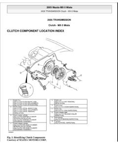
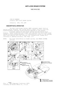
2 Control module also controls pump motor and self-diagnostic function. If a problem is detected in ABS, ABS will function like a conventional BRAKE system . ABS warning light will also come on. With detection of wheel lock-up, short pedal pulsations, occurring in rapid succession, will be felt in BRAKE pedal and steering wheel. Vehicle body may also vibrate slightly. These conditions are normal. Pedal pulsation will continue until there is no longer a need for ANTI-LOCK function or until vehicle is stopped. COMPONENT LOCATIONS COMPONENT LOCATIONS CAUTION: See ANTI-LOCK BRAKE SAFETY PRECAUTIONS article in GENERAL :For more information on BRAKE system , see BRAKE system Control ModuleUnder Carpet, Behind Passenger SeatData Link ConnectorLeft Side Of Engine CompartmentFront Sensor RotorOn Front Wheel HubHydraulic UnitRight Rear Of Engine CompartmentMotor & Valve RelaysOn Hydraulic UnitPump MotorOn Hydraulic UnitRear Sensor RotorOn Rear Drive AxleWheel Speed SensorOn Knuckle 1997 Mazda MX-5 Miata ANTI-LOCK BRAKE system 1997 BRAKES Mazda - ANTI-LOCK 1997 Mazda MX-5 Miata ANTI-LOCK BRAKE system 1997 BRAKES Mazda - ANTI-LOCK Microsoft Sunday, July 05, 2009 1:48.
3 48 PMPage 1 2005 Mitchell Repair Information Company, LLC. Microsoft Sunday, July 05, 2009 1:48:54 PMPage 1 2005 Mitchell Repair Information Company, LLC. BLEEDING BRAKE system 1. Raise and support vehicle. Ensure BRAKE fluid reservoir remains at least half full during bleeding procedure. When bleeding BRAKE system , start with longest brakeline first. Remove bleed screw cap. Connect one end of transparent vinyl tube to bleed screw. Submerge other end of tube in a container half filled with clean BRAKE fluid. 2. Have an assistant depress BRAKE pedal several times and hold in depressed position. Loosen bleed screw and drain fluid into container. Tighten bleed screw. 3. Refill BRAKE fluid reservoir if necessary.
4 Repeat step 2) until air is no longer discharged. Tighten bleed screw to 52-78 INCH lbs. ( ). Ensure fluid leakage is not present. Add fluid to reservoir. Repeat procedure for remaining wheels. TROUBLE SHOOTING Before attempting to diagnose vehicle, ensure ABS warning light is functioning properly. ABS warning light will not illuminate and ABS will not operate if battery voltage is insufficient. Perform trouble shooting procedures on ABS warning light to eliminate unnecessary repairs and/or component replacement. ABS WARNING LIGHT DOES NOT ILLUMINATE WHEN IGNITION IS TURNED ON 1. Turn ignition on. Check if other warning lights illuminate. If other warning lights do not illuminate, check METER fuse.
5 Replace as necessary. If other warning lights illuminate, check for possible malfunction and repair as necessary. Go to next step. 2. Turn ignition off. Disconnect ABS Control Module (ABS CM) connector. See COMPONENT LOCATIONS . Turn ignition on. Check if ABS warning light illuminates. If ABS warning light illuminates, go to next step. If ABS warning light does not illuminate, go to step 5). 3. Reconnect ABS CM connector. Turn ignition on. Check if ABS warning light illuminates. If ABS warning light does not illuminate, go to next step. If ABS warning light illuminates, a temporary poor contact in wiring may have occurred and ABS is now functioning properly. 4. Check if terminal AD of ABS CM harness connector is damaged or deformed.
6 See Fig. 3. If terminal AD is damaged or deformed, replace wiring harness connector. If terminal AD is okay, replace ABS CM. 5. With ABS CM connector disconnected, use a jumper wire and ground terminal AD of ABS CM harness connector. Check if ABS warning light illuminates. If ABS warning light illuminates, go to next step. If ABS warning light does not illuminate, go to step 7). 6. With ABS CM disconnected, check continuity between terminal AB of ABS CM harness connector and ground. Also, check continuity between terminal AC of ABS CM harness connector and ground, and CAUTION: DO NOT allow reservoir to run dry during BRAKE bleeding procedure. If BRAKE fluid is spilled, clean surface immediately with alcohol, as BRAKE fluid will damage painted surfaces.
7 Use only DOT 3 BRAKE fluid and DO NOT mix with any other :Ensure BRAKE pedal remains depressed until bleed screw is tightened. 1997 Mazda MX-5 Miata ANTI-LOCK BRAKE system 1997 BRAKES Mazda - ANTI-LOCK Microsoft Sunday, July 05, 2009 1:48:48 PMPage 2 2005 Mitchell Repair Information Company, LLC. between terminal AM of ABS CM harness connector and ground. If continuity exists, replace wiring harness connector. If continuity does not exist, repair wiring harness. 7. Check ABS warning light bulb. Replace bulb as necessary. If bulb is okay, go to next step. 8. Check continuity between terminal AD of ABS CM harness connector and terminal 1K of instrument cluster connector. See WIRING DIAGRAMS . If continuity exists, check ABS warning light.
8 See ABS WARNING LIGHT under COMPONENT TESTING . If continuity does not exist, repair wiring harness. ABS WARNING LIGHT REMAINS ILLUMINATED 1. Ensure battery is fully charged. Charge or replace as necessary. If battery is fully charged, go to next step. 2. Check ABS Control Module (ABS CM) connector for poor connection. Turn ignition on. Check if ABS warning light goes out. If ABS warning light does not go out, go to next step. If ABS warning light goes out, a temporary poor contact in wiring may have occurred and ABS is now functioning properly. 3. Turn ignition off. Disconnect ABS CM connector. See COMPONENT LOCATIONS . Measure voltage between terminals "A" and AB of ABS CM harness connector. See Fig.
9 3 . Also, measure voltage between terminals "A" and AC of ABS CM harness connector, and between terminals "A" and AM of ABS CM harness connector. If battery voltage is present, go to next step. If battery voltage is not present, repair wiring harness. 4. Connect ABS CM connector. Check for ABS DTCs. See RETRIEVING DIAGNOSTIC TROUBLE CODES under DIAGNOSIS & TESTING. If no DTCs are present, go to next step. 5. Turn ignition off. Disconnect ABS CM connector. Connect Harness Adapter (49-F066-022). Turn ignition on. Check if ABS warning light goes out. If ABS warning light does not go out, repair short in ABS warning light drive harness or instrument cluster. If ABS warning light goes out, replace ABS CM.
10 ABS WARNING LIGHT FLASHES WITH VEHICLE STOPPED 1. Ensure battery is fully charged. Charge or replace as necessary. If battery is fully charged, go to next step. 2. Check if a jumper wire is installed between terminals TBS and GND of Data Link Connector (DLC). See Fig. 1 . If jumper wire is installed, remove jumper wire from DLC. If jumper wire is not installed, go to next step. 3. Turn ignition off. Disconnect ABS Control Module (ABS CM) connector. See COMPONENT LOCATIONS . Check continuity between terminal "P" of ABS CM harness connector and ground. See Fig. 3 . If continuity exists, repair short to ground in DLC wiring harness. If continuity does not exist, replace ABS CM. NOTE:ABS warning light will illuminate if voltage between terminal "A" (voltage supply) of ABS CM harness connector and ground is less than about 10 volts.