Transcription of Cavity Shaftwall Systems - nationalgypsum.com
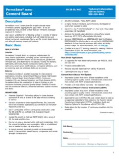
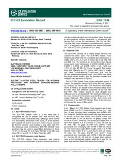
1 09 21 Cavity Shaftwall Systems12 THEDITION09 21 Shaftwall SYSTEMSJ TRACKI-STUD, C-T or C-H1" FIRE-SHIELDSHAFTLINERJ TRACK1/2" FIRE-SHIELD CGYPSUMBOARDCAVITY Shaftwall SYSTEMU497-2 Hour (fire-tested both sides) Cavity Shaftwall SYSTEMSDESCRIPTIONTECHNICAL SizeBase SteelAYIS2 1/2" ( mm) " 1/2" ( mm) " " (102 mm) " " (102 mm) " " (152 mm) " properties are in accordance with AISI Specifications For the Design ofCold-Formed Steel Structural Members. I-STUD SECTION PROPERTIES ABOUT X-X AXISA= Section Area, Distance from neutral axis to extreme steel fiber, = Moment of Inertia, Section Modulus, properties based on steel without drywall shaftconstruction has becomethe preferred alternative totraditional masonry Shaftliner boardwas developed as alightweight, easy-to-installreplacement for masonry inthe interior core ofbuildings for shaftwalls,stairwells, other verticalchases and mechanicalenclosures.
2 Shaftliner board is also used as acomponent of 2" solidpartitions, and areaseparation walls with alayer of 1/2" Regular orFire-Shield Gypsum Boardattached to each , heavy masonryweighing 20 to 45 lbs. persquare foot was used forshaftwall the use of Shaftliner, Shaftwall assemblies weighin at a remarkably low 10to 13 lbs. per square benefits of gypsumdrywall shaft Systems go farbeyond the difference inweight alone. The corewall of a shaft can beinstalled from the exteriorof the shaft and requires no scaffolding. Erection is speedy and also providesexcellent sound controland can achieve the fireratings necessary for today sbuilding construction. Bestof all, gypsum shaftwallsystems are moreeconomical than masonryshaft Gypsum producesShaftliner board with greenmoisture-resistant paper orpurple moisture/mold/mildew resistant paper onboth sides with a bevelededge configuration allowingfor simple installation intothe Shaftwall Shaftwall Systems are anonload-bearing drywallpartition made up of twobasic components, gypsumboard and metal board includes 1"Fire-Shield Shaftliner or 1"Fire-Shield Shaftliner XPpanels, 1/2" Fire-Shield Cand 5/8" Fire-ShieldGypsum Board face " XP Fire-Shield C or 5/8"XP Fire-Shield GypsumBoard face panels may beutilized for extra protectionagainst mold and framing includes I-Studs.
3 C-T Studs and C-Hstuds with integraltabs/flange which hold thepanels in place and J Trackfor runners at top andbottom, as well as verticallyat partition ends and toframe Cavity Shaftwall Systemswere developed to encloseelevator shafts and othervertical chases in buildingswhere it is advantageous toerect these walls from oneside only and where fireresistance and resistance toair pressures are Gypsum CompanyCavity Shaftwall Systemsmay be constructed with C-T, C-H or I-Stud ShaftwallSystems are very lightweightcompared to conventionalshaftwalls, weighingapproximately 10 lbs. persq. ft. of wall when finishedwith two layers of 1/2" Fire-Shield CGypsum can bequickly enclosed with Shaftwall framing andShaftliner under mostconditions in whichinstallers can work, wellbelow temperaturelimitations for finish gypsumboard 1" Shaftliner is faced with light greenmoisture-resistant paper andShaftliner XP is faced withpurple moisture/mold/mildew resistant paper forprotection against weatherduring Code ReportReferences:ICC ES, Inc.
4 Legacy Report ES, Inc. Legacy Report 9525 BICBO ES, ER-3579 FUNCTION AND UTILITYL oading the cavityshaftwall Systems are non-load-bearing, this Systemhas been designed andtested to withstand positiveand negative air pressureforces exerted by high-speed, high-rise cavityshaftwall Systems havebeen fire tested and haveachieved fire resistanceratings of 1 and 2 hours. Allcomponents arenoncombustible. Refer to pages 19 and GA (.020" minimum steelthickness) J Track exceeded2,000,000 lateral loadoscillation cycles in a testconducted to duplicate thepositive and negativepressures created aselevator cabs rise anddescend in a shaft. Sound ratings of 40 to 51 havebeen achieved in testsconducted in accordancewith ASTM E 90. Refer to pages 19 and The Cavity Shaftwall systemsshould not be used whereexposed to constantdampness or conditionsunder which free water canbe This System should not beexposed to temperatures over 125 F for extendedperiods of Where reference is made tonominal gauges, 25 gaugerelates to minimum basesteel of.
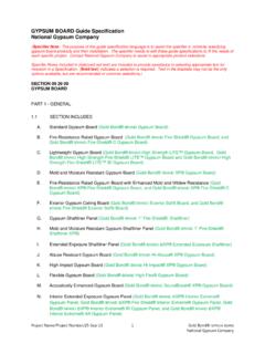
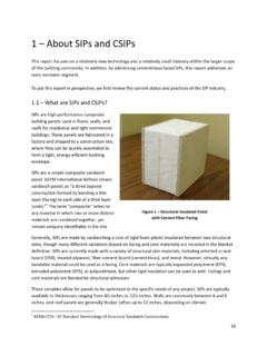
5 020" and 20 gaugeto .0329". CAULK WHEREREQUIREDNote: In addition to National Gypsum Systems , 1/2" Fire-Shield C,5/8" Fire-Shield and 1" Fire-Shield Shaftliner panels arelisted in Dietrich Industries ICC ES Legacy Report NER-506, Shaftwall and Stairwell Fire-Resistive (C-T stud) Shaftwall SYSTEMS09 21 21 /NGCU498 2 HOURSTAIRWELL CONSTRUCTION1" FIRE-SHIELDSHAFTLINERJ TRACK .020", .0329"(3" LEG .0329" ONLY)VIEW A-AI-STUD .020", .0329"U499 1 HOURSHAFTWALLALLOWABLE WALL HEIGHTS FOR 1-HOUR FIRE-RATED I-STUD ASSEMBLIESStudStudMin. SteelSustained Air Pressure Load PSFSizeSpacingThicknessAllowablein. (mm)in. (mm) 1/2"24" '- 4" (4060 mm)11'- 7" (3531 mm)10'- 1" (3073 mm)8'- 3" (2515 mm)( mm)(610 mm)L/24010'- 7" (3226 mm)9'- 3" (2819 mm)8'- 5" (2565 mm)7'- 4" (2235 mm)L/3609'- 3" (2819 mm)8'- 1" (2464 mm)7'- 4" (2235 mm)6'- 5" (1956 mm)2 1/2"24" L/12015'- 2" (4623 mm)13'- 3" (4039 mm)12'- 1" (3683 mm)10'- 7" (3226 mm)( mm)(610 mm)L/24012'- 1" (3683 mm)10'- 7" (3226 mm)9'- 7" (2921 mm)8'- 4" (2540 mm)L/36010'- 7" (3226 mm)9' - 2" (2794 mm)8'- 4" (2540 mm)7'- 4" (2235 mm)4"24" L/12017'- 11" (5461 mm)14'- 10" (4521 mm)12'- 10" (3912 mm)9'- 9" (2972 mm)(102 mm)(610 mm)L/24014'- 3" (4343 mm)12'- 5" (3785 mm)11'- 4" (3454 mm)9'- 5" (2870 mm)L/36012'- 5" (3785 mm)10'- 10" (3302 mm)9'- 5" (2870 mm)8'- 3" (2515 mm)4"24" L/12020'- 0" (6096 mm)18'- 2" (5537 mm)16'- 6" (5029 mm)
6 14'- 3" (4343 mm)(102 mm)(610 mm)L/24016'- 6" (5029 mm)14'- 5" (4394 mm)13'- 1" (3988 mm)11'- 5" (3480 mm)L/36014'- 5" (4394 mm)12'- 7" (3835 mm)11'- 5" (3480 mm)9'- 4" (2845 mm)6"24" L/12024'- 0" (7315 mm)22'- 10" (6960 mm)19'- 9" (6020 mm)16'- 2" (4928 mm)(152 mm)(610 mm)L/24020'- 11" (6375 mm)18'- 4" (5588 mm)16'- 8" (5080 mm)14'- 6" (4420 mm)L/36018 - 4" (5588 mm)16'- 0" (4877 mm)14'- 6" (4420 mm)10'- 11" (3327 mm)ALLOWABLE WALL HEIGHTS FOR 2-HOUR FIRE-RATED I-STUD ASSEMBLIES UNLINED RETURN AIR SHAFTSStudStudMin. SteelSustained Air Pressure Load PSFSizeSpacingThicknessAllowablein. (mm)in. (mm) 1/2"24" '- 7" (4445 mm)12'- 4" (3759 mm)10'- 9" (3277 mm)8'- 9" (2667 mm)( mm)(610 mm)L/24011'- 7" (3531 mm)10'- 1" (3073 mm)9'- 2" (2794 mm)8'- 0" (2438 mm)L/36010'- 1" (3073 mm)8'- 10" (2692 mm)8'- 0" (2438 mm)7'- 0" (2134 mm)2 1/2"24" '- 9" (5410 mm)15'- 6" (4724 mm)14'- 1" (4293 mm)12'- 4" (3759 mm)( mm)(610 mm)L/24014'- 1" (4293 mm)12'- 4" (3759 mm)11'- 2" (3404 mm)8'- 9" (3404 mm)L/36012'- 4" (3759 mm)9'- 8" (2946 mm)8'- 9" (2667 mm)7'- 8" (2337 mm)4"24" '- 10" (6045 mm)16'- 3" (4953 mm)14'- 0" (4267 mm)10'- 2" (3099 mm)(102 mm)(610 mm)L/24016'- 2" (4928 mm)14'- 2" (4318 mm)11'- 6" (3505 mm)10'- 0" (3048 mm)L/36014'- 2" (4318 mm)11'- 0" (3353 mm)10'- 0" (3048 mm)8'-9" (2667 mm)4"24" '- 2" (7061 mm)20'- 2" (6147 mm)18'- 1" (5512 mm)14'- 9" (4496 mm)(102 mm)(610 mm)
7 L/24018'- 4" (5588 mm)16'- 1" (4902 mm)14'- 7" (4445 mm)11'- 1" (3378 mm)L/36016'- 1" (4902 mm)14'- 0" (4267 mm)11'- 1" (3378 mm)9'- 8" (2946 mm)6"24" '- 0" (8534 mm)23'- 11" (7290 mm)20'- 9" (6325 mm) 16'- 11" (5156 mm)(152 mm)(610 mm)L/24022'- 9" (6934 mm)19'- 10" (6045 mm)18'- 0" (5486 mm) 12'-10" (3912 mm)L/36019'- 10" (6045 mm)17'- 4" (5283 mm) 12'- 10" (3912 mm)11'- 2" (3404 mm) Yield strength 40,000 psiLimiting heights are based on transverse load tests (in accordance with ASTM E 72) and calculated utilizing the loads indicated. Yield strength 40,000 psiLimiting heights are based on transverse load tests (in accordance with ASTM E 72) and calculated utilizing the loads Shaftwall SYSTEMSALLOWABLE WALL HEIGHTS FOR 2-HOUR FIRE-RATED I-STUD Air Pressure Load PSFSizeSpacingSteelAllowablein.
8 (mm)in. (mm) 1 '- 3"f (4648 mm)12'- 6"f (3810 mm)10'- 9"f (3276 mm)8'-10"f (2692 mm)( mm)(610 mm)L/24012'- 6" (3810 mm)11'- 0" (3352 mm)10'- 0" (3048 mm)8'- 9" (2667 mm)L/36011'- 0" (3352 mm)9'- 6" (2895 mm)8'- 8" (2641 mm)7'- 7" (2311 mm)2 1 '-10" (5435 mm)15'- 8" (4775 mm)14'- 2"f (4318 mm)*12'- 5" (3784 mm)( mm)(610 mm)L/24014'- 2" (4318 mm)12'- 5" (3784 mm)11'- 4" (3454 mm)9'-10" (2997 mm)L/36012'- 5" (3784 mm)10'-11" (3327 mm)9'-10" (2997 mm)8'- 7" (2616 mm) '- 4" (6197 mm)16'- 8"f (5080 mm)*14'- 5"f (4394 mm)*11'-10"f (3606 mm)(102 mm)(610 mm)L/24016'- 1" (4902 mm)14'- 1" (4292 mm)12'-10" (3911 mm)*11'- 2" (3403 mm)L/36014'- 1" (4292 mm)12'- 4" (3759 mm)11'- 2" (3403 mm)* 9'-10" (2997 mm) '-10" (4114 mm)*19'- 1" (5816 mm)*17'- 4" (5283 mm)*15'- 1" (4597 mm)(102 mm)(610 mm)
9 L/24017'- 4" (5283 mm)15'- 1" (4597 mm)13'-10" (4216 mm)*12'- 0" (3657 mm)L/36015'- 1" (4597 mm)13'- 2" (4013 mm)12'- 0" (3657 mm)*10'- 6" (3200 mm) '- 4" (7721 mm)*22'- 1" (6731 mm)*20'- 1" (6121 mm)*17'- 6" (5334 mm)(152 mm)(610 mm)L/24020'- 1" (6121 mm)*17'- 6" (5334 mm)*15'-11" (4851 mm)*13'-11" (4241 mm)L/36017'- 6" (5334 mm)15'- 4" (4673 mm)13'-11" (4241 mm)*12'- 2" (3708 mm)f Limited by bending stress Yield strength 40,000 psi v Limited by end reaction relating to stud or track Unless noted, heights are limited by deflection.* 20 gauge track required For heights limited by bending stress, allowable bending stresses have been increased for intermittent loading. Heights limited by deflection are based on transverse load tests (in accordance with ASTM E 72) and calculated utilizing the loads WALL HEIGHTS FOR 2-HOUR FIRE-RATED I-STUD ASSEMBLIES STAIRWELLSStudStudMin.
10 SteelSustained Air Pressure Load PSFSizeSpacingThicknessAllowablein. (mm)in. (mm) 1/2"24" '- 11" (4242 mm)12'- 2" (3708 mm)11'- 0" (3353 mm)9'- 8" (2946 mm)( mm)(610 mm)L/24011'- 0" (3353 mm)9'- 8" (2946 mm)8'- 9" (3404 mm)7'- 8" (2337 mm)L/3608'- 9" (2946 mm)8'- 5" (2565 mm)7'- 8" (2337 mm)6'- 8" (2032 mm)2 1/2"24" '- 7" (5055 mm)14'- 6"f (4420 mm)13'- 2"f (4013 mm)11'- 6" (3505 mm)( mm)(610 mm)L/24013'- 2" (4013 mm)11'- 6" (3505 mm)9'- 10" (2897 mm)8'- 7" (2616 mm)L/36011'- 6" (3505 mm)10'- 0" (3048 mm)8'- 7" (2616 mm)7'- 6" (2286 mm)4"24" '- 2" (6147 mm)17'- 8" (5385 mm)16'- 0" (4877 mm)11'- 11" (3632 mm)(102 mm)(610 mm)L/24016'- 0" (4877 mm)11'- 11" (3632 mm)10'- 10" (3302 mm)9'- 5" (2870 mm)L/36011'- 11" (3632 mm)10'- 6" (3175 mm)9'- 5" (2870 mm)8'- 3" (2515 mm)4"24" '- 3" (6782 mm)19'- 6" (5944 mm)17'- 8" (5385 mm)15'- 6" (4724 mm)(102 mm)