Transcription of CE & UL Version Service manual Electric and Gas Combi
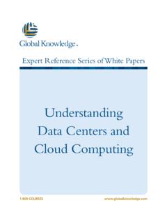
1 SmartCombi ServiceCE & UL VersionService manualElectric and Gas Combi2008/07/28 SEV/KAModelSerial-No. / datefromthruElectric:ESC 61507020594 ESC 62007020594 ESC 11507020594 ESC 12007020594 ESC 21507020594 ESC 220 07020594 Gas:GSC 61507020594 GSC 62007020594 GSC 11507020594 GSC 120 07020594 GSC 21507020594 GSC 220 07020594 From software ServicePrepositionThe documentation may address the ovens as , and These represent the size of the units in regards as the number of Penny is using the following model numbers615620115120215220 These are equivalent to the (61) (62) (101) (102) (201) (202) 220 DynaSteam =AST (AdvanceSteamTechnology)
2 AutoChef = SmartMenuCombiPilot = CombiDial2 SmartCombi diagram of the DynaSteam automatic cleaning system WaveClean to open the Front Panel and the Side location / (left side view)..9 Parts location / Gas (left side view)..10 Parts location Electric (left side view)..11 Parts location Electric (front view)..12 DynaSteam unit of the gas of the heating process regular operating ..19 Diagram of the heating process no gas present ..20 Diagram of the heating process gas present, no flame detection ..21CO2 value orifices and fan speeds orifices and fan speeds gas supply of the connection pressure (operating pressure).
3 27 Rearrangement of the gas type ..28 Adjustment of the cabinet and compatibility summary of temperature of the frequency main menu (Password overview & diagnosis memory) ..33 Service menu of the electronic (Configuration menu)..34 Settings area (basic settings)..44 Generally measurement mask for Electric measurement mask for gas to activate and disable the demo mode ..52 Reset of the a performance optimization system (LOA) ..52 Connection of external facilities to the potential-free contact ..52 How to change the display of relay pcb A1 Electric & Gas of relay pcb Electric & Gas of keyboard pcb A2 Electric ..58 Layout of keyboard pcb A2 Gas.
4 59 Fuse protection schematic for CE protection schematic for UL Electric -Units (208V)..61 Fuse protection schematic for UL Gas-Units (120V)..62 Reserve relay K 17 rewiring UL unit Set Service4 SmartCombi ServiceFunctional diagram of the DynaSteam technology1)The pcb controls the DynaSteam unit which is responsible for the amount of injected water. The incoming water flow pressure must be between 1,5 (21,75 psi) and 6 bar (87,00 psi). The pressure switch controls the availability and the pressure of )The heat exchanger heats the steam water up to 50 C (122 F) and cools down the out coming heat from the chamber to save cooling )The preheated water runs now in a hose to the water supply pipe located in the chamber.
5 In side the hose there is an orifice to stabilize the pulsed water flow from the water steaming )Now the water supply pipe injects the water on an centrifuge at the PHI fan wheel. The heating elements surround the fan wheel heats it up. The water gets to steam now and by the speed of the fan wheel tiny drops are flung against the chamber. Surplus water runs into the : - During heat up and after opening / closing the door during operation the steaming unit increases the amount of water to speed up the steam production (controlled by the electronic).- At a temperature <107 C (225 F) the steaming unit decreases the amount of water (electronic controlled).
6 Water consumption during permanently steaming:unit / water volume in ml/h75001600021000180002400018000 1800024000 240005 SmartCombi ServiceThe automatic cleaning system WaveClean IIOperational sequence of the cleaning systemAt the fully automatic cleaning WaveClean the following cleaning programmes can be chosen: Short: Last approx. 60 minutes Normal: Last approx. 110 minutes Extra: Last approx. 180 minutesSchematic diagram example / on exit temperature the chamber cooling down to 55 C (131 F)02-Cleaning of the siphon by water exchange. The pump M24 pumps out the water from the siphon. The siphon gets filled with water about the solenoid valve Y12.
7 This process recurs repeatedly. This process serves for cleaning the pre-cleaning of the chamber by changing the water radically above pump starts after a time of 6 minutes. The chamber heated at the same time . The cleaner activates at a temperature of 70 C (158 F). A cancellation of the cleaning process is not possible in this phase!6 Pump M24 Pump M16 Valve Y12 SmartCombi ServiceContinuation description WaveClean II StepDescription05-Execution of cleaning. The fan runs in a right/left direction of rotation as well as in a slow/fast speed. The pump M16 permanently changes the water radically. The running time depends on the chosen cleaning of the siphon by water exchange.
8 The pump M24 pumps out the water from the siphon. The siphon gets filled with water about the solenoid valve Y12. The process recurs repeatedly. This process serves for cleaning the siphon. Fresh water is changed radically over the pump M16 to rinse the chamber. The fan runs in a right/left direction of rotation as well as in a slow/fast chamber heats up to 92 C (198 F). The rinse wax layer smelting now. The rinse granulate falls into the chamber now. A cancellation of the cleaning process is not possible in this phase!08-The rinsing program starts. The fan runs in a right/left direction of rotation as well as in a slow/fast speed.
9 The pump M16 permanently changes the water radically. The running time depends on the chosen cleaning of the siphon by water exchange. The pump M24 pumps out the water from the siphon. The siphon gets filled with water about the solenoid valve Y12. This process recurs repeatedly. This process serves for cleaning the siphon. Fresh water is changed radically over the pump M16 to rinse the chamber. The fan runs in a right/left oven starts in steam mode for four minutes to prepare final rinsing. After this the final rinsing chamber dried with hot air for 10 minutes. Thereby the chamber heats up to 105 C (221 F). When cleaning with "short-program" this step is device turns off itself now.
10 Cleaning is : During cleaning approx. 3 litres of water are led by the soft water assembly group to rinse out possible cleaner an interruption of the power supply the cleaning process stopped automatically. A "cancellation program" which rinses out the cooked room is started with a duration of 12 program is carried out also at a manual entry is written down in the diagnostic and HACCP ServiceHow to open the Front Panel and the Side WallsDismounting of Side Walls:After dismounting of the two screws, the respective side wall can be of the Front Panel: The Front Panel will be unlocked by turning the hexagon socket clockwise. Lift up the Front Panel careful and open screwsHexagon screw2 screwsSmartCombi ServiceParts location / (left side view)CE Version9 Lift magnet Y8 Safty limit switch F7 Fan M1 Heating element Humidity probeB5transformer T1 Solid state relaisV1/V2 heating systemSolid state relais V3(chamber lighting) Cooling fan M7 Drain probe B4 WaveClean pump M16 Cold water assemblySolenoid valve Y12 DynaSteam unitNot mapped: (position in front of the trap.)