Transcription of Ceiling and Cabinet Fans - Loren Cook Company
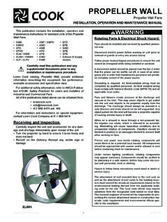
1 GEMINI. Ceiling and Cabinet fans INSTALLATION, OPERATION AND MAINTENANCE MANUAL. This publication contains the installation, operation and maintenance instructions for standard units of the Gemini: Ceiling and Cabinet fans . Rotating Parts & Electrical Shock Hazard: Carefully read this publication and any fans should be installed and serviced by qualified person- supplemental documents prior to any nel only. installation or maintenance procedure. Loren Cook catalog, Gemini, provides additional infor- Disconnect electric power before working on unit (prior to removal of guards or entry into access doors). mation describing the equipment, fan performance, avail- able accessories and specification data. Follow proper lockout/tagout procedures to ensure the unit For additional safety information, refer to AMCA Publica- cannot be energized while being installed or serviced. tion 410-96, Safety Practices for Users and Installers of Industrial and Commercial fans .
2 A disconnect switch should be placed near the fan, so All of the publications listed above can be obtained from: power can be swiftly turned off in case of an emergency. This will also allow maintenance personnel to have com- plete control of the power source. 417-869-6474 ext. 166 Grounding is required. All field-installed wiring must be completed by qualified personnel. All field installed wiring For information and instructions on special equipment, must comply with National Electric Code (NFPA 70) and all contact Loren Cook Company at 417-869-6474. applicable local codes. fans and blowers create pressure at the discharge and vacuum at the inlet. This may cause objects to get pulled into the unit and objects to be propelled rapidly from the discharge. The discharge should always be directed in a safe direction and inlets should not be left unguarded. Any object pulled into the inlet will become a projectile capable of causing serious injury or death.
3 When air is allowed to move through a non-powered fan, the impeller can rotate. This is referred to as windmilling. This unexpected rotation of components can cause a haz- ardous condition. Impellers should be blocked in position or air passages blocked to prevent draft prior to working on fans . Friction and power loss inside rotating components can cause them to be a potential burn hazard. All components Gemini 100 should be approached with caution and/or allowed to cool before contacting them for maintenance. Receiving and Inspection Under certain lighting conditions, rotating components Carefully inspect the fan and accessories for any may appear stationary. Components should be verified to be stationary in a safe manner, before they come into con- damage and shortage immediately upon receipt of fan. tact with personnel, tools or clothing. Turn the wheel by hand to ensure it turns freely and does not bind.
4 Failure to follow these instructions could result in death or Inspect dampers (if included) for free operation of all serious injury. moving parts. Remove mounting brackets from packing insert & install mounting brackets (Gemini 100 only). Remove shipping tape. Record on the Delivery Receipt any visible sign of damage. Handling Lift fan by grasping the outside housing ( Cabinet ) or by the blower mounting brace. Never lift by the shaft or motor. GEMINI IO&M 1 B51111-002. Storage Direction of Discharge (200 900 Series). If the fan is stored for any length of time prior to Discharge direction can be converted from right angle to installation, store it in its original shipping crate and protect straight line, without a kit, by swapping outer panel and the it from dust, debris and the weather. inlet/grille: See Figure 1. 1. Remove the side panel, mounting brackets (2) and Installation grille (if present).
5 Motor Installation 2. Place the side panel where the inlet/grille had been. All Gemini units are shipped with motors mounted at the Place the mounting brackets on the edge where the factory. side panel had been. Holes are pre-punched for this procedure. Gemini 100 Inline to Ceiling Conversion 3. Rotate unit so that the outlet is on top. The Gemini 100 series can be converted from inline to Ceiling by ordering the Inline to Ceiling Conversion Kit Figure 1. from Loren Cook Company (Part Number 797180). The kit Start Outlet includes all parts required, plus detail instructions on how to convert the Gemini 100. Gemini 100 Ceiling to Inline Conversion The Gemini 100 series can be field converted from Inlet Ceiling to inline by following these steps: Remove Parts 1. Remove and discard the inlet box end plate. 2. Install the inline cover panel with sheet metal screws as shown on the following page.
6 Ceiling to Inline Conversion Kit can be ordered from Loren Cook Company (Part Number 797181), or fabricate the required part using the following two sketches. x2. 18 Ga. Galvanized Steel Replace Parts 16-3/4 14-1/16 Outlet 13-15/16 1-3/8. 11-15/16. 13-5/16. 12. Bend up at 90o Inlet 1-7/16. (Inches) Fan Installation Flat Pattern Finished Views 1. Use the mounting bracket slots to lower the unit housing by a distance equal to the Ceiling thickness. Refer to Figure 2. 2. Raise the unit, as needed to accommodate acces- sories and options: With optional filter, raise unit 3/8 . For both filter and deluxe aluminum grille options, raise unit 7/8 to compensate for 1/2 grate protru- sion of grille. If filter is not present: the grate on the aluminum grille will fit inside of the unit (except sizes 160 & 180). Other grilles have no protrusion and fit flush with the fan. 3. Fasten duct work to the outside of the duct collar (damper frame) using sheet metal screws and foil tape.
7 Make sure sheet metal screws are placed where they do not interfere with damper operation. Inline 4. Fasten the housing to the bottom of the joists through Cover Panel the holes provided in the mounting bracket. For Ceiling Radiation Damper Installation see separate document, Gemini/CRD. Installation Supplement.. GEMINI IO&M 2 B51111-002. Typical Installation Roof Roof jack with damper or roof cap Exterior Wall Use foil tape 6 round duct. Insulated duct will help on the joints absorb vibration. Use the shortest runs to ensure a possible & long radius elbows. good seal. Joists Wall cap Power with damper cord or Short (1') piece of flexible duct Seal around the will absorb vibration & noise. unit with caulk. Insulation around unit. Also, cover the fan with insulation. Figure 2 Ensure the power supply (voltage, frequency and current carrying capacity of wires) is in accordance with the motor Unit Housing nameplate.
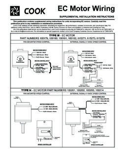
8 Refer to Wiring Diagrams. Lock out all power sources before unit is wired to power Joists source. Mounting Follow the wiring diagram in the disconnect Bracket switch and the wiring diagram provided with the Ceiling motor. Correctly label the circuit on the main power box and always identify a closed switch Grate Protrusion (aluminum grille only) to promote safety ( , red tape over a closed Filter (optional). switch). Grille Note: Insulate Unused Leads. Fan plug box is designed for single speed operation, using an FSC to vary speed if required. Do not wire to more than two leads. Notice! Do not install above or around Wiring Diagrams cooking equipment (shaded area) Gemini 100 Series: Cap off wire that is not in use. 45O 45O. Red Wire (Low Speed). Black Wire (High Speed). Green Wire (Ground by COOK). Cooking Equipment White Wire (Common) Ground Screw for Floor Field Grounding Wiring Installation All wiring should be in accordance with local ordinances and the National Electrical Code, NFPA 70.
9 For fan power supply connection use 4-wire cable provided in field wiring box shown on above diagram. GEMINI IO&M 3 B51111-002. Connect field ground wire to green ground screw located Gemini 1000: inside fan electrical box. Connect one supply line to white 1 PH / 60 HZ / 115V 1 PH / 60 HZ / 208-230 V. wire. Depending on fan speed requirements connect other MARATHON AMPS MARATHON AMPS. supply line to Red wire for Low Speed or Black wire for Purple Line 1 Purple Line 1. High Speed. Insulate unused Red or Black wire. Replace White Line 2. Yellow Line 2. electrical box cover. Model 126, 146, 166, 186 are Low Yellow Brown Insulate Speed. Models 128, 148, 168, 188 are High Speed. Orange Orange Insulate Insulate Brown White Gemini 200, 300, 500, 600 and 700 Series: 1 PH / 60 HZ / 115V 1 PH / 60 HZ / 208-230 V. White Line MAGNETEK AMPS MAGNETEK AMPS. Black Line 1 Purple Insulate Black (High) White Yellow Line 2.
10 Red Blue Line 2. Red (Low) Line Blue Orange Insulate Line 1. Orange White 3 PH / 60 HZ / 208-230 V. MARATHON AMPS. MAGNETEK AMPS. Electrical Shock & Fire Hazard: T4. Insulate T1. Line 1. Insulate Unused Leads Separately P4 T7. T5 T2. Failure to follow these instructions could result in Insulate Line 2. death or serious injury. P6 T8. T6 T3 Line 3. Insulate P6 T9. Gemini 400 Series: 3 PH / 60 HZ / 460 V. White Line MARATHON AMP. MAGNETEK AMP. Black Line T4 T1 Line 1. Insulate T7 T2 Line 2. Gemini 500, 700 and 900 with Vari-Flow EC Motor: T6 T3 Line 3. Insulate T9 P4 Insulate T5 P5 Insulate Insulate T8 P6 Insulate Gemini 2000: 1 PH / 60 HZ / 115V 1 PH / 60 HZ / 208-230 V. MARATHON AMPS MARATHON AMPS. Purple Line 1 Orange Line 1. For external motor control see Brown Brown Insulate Insulate External Control Supplement. Blue Blue Insulate White White Line 2. Black Black Line 2.