Transcription of Centrifugal Pumps: Basic Concepts of Operation ...
1 Centrifugal pumps : Basic Concepts of Operation , Maintenance, and Troubleshooting (Part- I). Introduction The operating manual of any Centrifugal pump often starts with a general statement, Your Centrifugal pump will give you completely trouble free and satisfactory service only on the condition that it is installed and operated with due care and is properly maintained.. Despite all the care in Operation and maintenance, engineers often face the statement the pump has failed it can no longer be kept in service . Inability to deliver the desired flow and head is just one of the most common conditions for taking a pump out of service. There are other many conditions in which a pump, despite suffering no loss in flow or head, is considered to have failed and has to be pulled out of service as soon as possible. These include seal related problems (leakages, loss of flushing, cooling, quenching systems, etc), pump and motor bearings related problems (loss of lubrication, cooling, contamination of oil, abnormal noise, etc), leakages from pump casing, very high noise and vibration levels, or driver (motor or turbine) related problems.
2 The list of pump failure conditions mentioned above is neither exhaustive nor are the conditions mutually exclusive. Often the root causes of failure are the same but the symptoms are different. A little care when first symptoms of a problem appear can save the pumps from permanent failures. Thus the most important task in such situations is to find out whether the pump has failed mechanically or if there is some process deficiency, or both. Many times when the pumps are sent to the workshop, the maintenance people do not find anything wrong on disassembling it. Thus the decision to pull a pump out of service for maintenance / repair should be made after a detailed analysis of the symptoms and root causes of the pump failure. Also, in case of any mechanical failure or physical damage of pump internals, the operating engineer should be able to relate the failure to the process unit's operating problems. Any operating engineer, who typically has a chemical engineering background and who desires to protect his pumps from frequent failures must develop not only a good understanding of the process but also thorough knowledge of the mechanics of the pump.
3 Effective troubleshooting requires an ability to observe changes in performance over time, and in the event of a failure, the capacity to thoroughly investigate the cause of the failure and take measures to prevent the problem from re-occurring. Centrifugal pumps : Basics Concepts of Operation , Maintenance, and Troubleshooting, Part I. By: Mukesh Sahdev, Associate Content Writer Presented at The Chemical Engineers' Resource Page, The fact of the matter is that there are three types of problems mostly encountered with Centrifugal pumps : design errors poor Operation poor maintenance practices The present article is being presented in three parts, covering all aspects of Operation , maintenance, and troubleshooting of Centrifugal pumps . The article has been written keeping in mind the level and interests of students and the beginners in Operation . Any comments or queries are most welcome. Working Mechanism of a Centrifugal Pump A Centrifugal pump is one of the simplest pieces of equipment in any process plant.
4 Its purpose is to convert energy of a prime mover (a electric motor or turbine) first into velocity or kinetic energy and then into pressure energy of a fluid that is being pumped. The energy changes occur by virtue of two main parts of the pump, the impeller and the volute or diffuser. The impeller is the rotating part that converts driver energy into the kinetic energy. The volute or diffuser is the stationary part that converts the kinetic energy into pressure energy. Note: All of the forms of energy involved in a liquid flow system are expressed in terms of feet of liquid head. Generation of Centrifugal Force The process liquid enters the suction nozzle and then into eye (center) of a revolving device known as an impeller. When the impeller rotates, it spins the liquid sitting in the cavities between the vanes outward and provides Centrifugal acceleration. As liquid leaves the eye of the impeller a low-pressure area is created causing more liquid to flow toward the inlet. Because the impeller blades are curved, the fluid is pushed in a tangential and radial direction by the Centrifugal force.
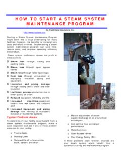
5 This force acting inside the pump is the same one that keeps water inside a bucket that is rotating at the end of a string. Figure below depicts a side cross-section of a Centrifugal pump indicating the movement of the liquid. Centrifugal pumps : Basics Concepts of Operation , Maintenance, and Troubleshooting, Part I. By: Mukesh Sahdev, Associate Content Writer Presented at The Chemical Engineers' Resource Page, Figure : Liquid flow path inside a Centrifugal pump Conversion of Kinetic Energy to Pressure Energy The key idea is that the energy created by the Centrifugal force is kinetic energy. The amount of energy given to the liquid is proportional to the velocity at the edge or vane tip of the impeller. The faster the impeller revolves or the bigger the impeller is, then the higher will be the velocity of the liquid at the vane tip and the greater the energy imparted to the liquid. This kinetic energy of a liquid coming out of an impeller is harnessed by creating a resistance to the flow.
6 The first resistance is created by the pump volute (casing) that catches the liquid and slows it down. In the discharge nozzle, the liquid further decelerates and its velocity is converted to pressure according to Bernoulli's principle. Therefore, the head (pressure in terms of height of liquid) developed is approximately equal to the velocity energy at the periphery of the impeller expressed by the following well-known formula: Centrifugal pumps : Basics Concepts of Operation , Maintenance, and Troubleshooting, Part I. By: Mukesh Sahdev, Associate Content Writer Presented at The Chemical Engineers' Resource Page, A handy formula for peripheral velocity is: This head can also be calculated from the readings on the pressure gauges attached to the suction and discharge lines. Pump curves relate flow rate and pressure (head). One fact that must always be developed by the pump at different impeller sizes remembered: A pump does and rotational speeds. The Centrifugal pump not create pressure, it only Operation should conform to the pump curves provides flow.
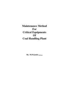
7 Pressure is a supplied by the manufacturer. In order to read and understand the pump curves, it is very just an indication of the important to develop a clear understanding of the amount of resistance to flow. terms used in the curves. This topic will be covered later. Centrifugal pumps : Basics Concepts of Operation , Maintenance, and Troubleshooting, Part I. By: Mukesh Sahdev, Associate Content Writer Presented at The Chemical Engineers' Resource Page, General Components of Centrifugal pumps A Centrifugal pump has two main components: I. A rotating component comprised of an impeller and a shaft II. A stationary component comprised of a casing, casing cover, and bearings. The general components, both stationary and rotary, are depicted in Figure The main components are discussed in brief below. Figure shows these parts on a photograph of a pump in the field. Figure : General components of Centrifugal Pump Centrifugal pumps : Basics Concepts of Operation , Maintenance, and Troubleshooting, Part I.
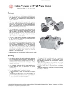
8 By: Mukesh Sahdev, Associate Content Writer Presented at The Chemical Engineers' Resource Page, Figure : Gene ral components of a Centrifugal Pump Stationary Components Casing Casings are generally of two types : volute and circular. The impellers are fitted inside the casings. 1. Volute casings build a higher head; circular casings are used for low head and high capacity. o A volute is a curved funnel increasing in area to the discharge port as shown in Figure As the area of the cross-section increases, the volute reduces the speed of the liquid and increases the pressure of the liquid. Centrifugal pumps : Basics Concepts of Operation , Maintenance, and Troubleshooting, Part I. By: Mukesh Sahdev, Associate Content Writer Presented at The Chemical Engineers' Resource Page, Figure : Cut-away of a pump showing volute casing o One of the main purposes of a volute casing is to help balance the hydraulic pressure on the shaft of the pump. However, this occurs best at the manufacturer's recommended capacity.
9 Running volute-style pumps at a lower capacity than the manufacturer recommends can put lateral stress on the shaft of the pump, increasing wear-and-tear on the seals and bearings, and on the shaft itself. double - volute casings are used when the radial thrusts become significant at reduced capacities. 2. Circular casing have stationary diffusion vanes surrounding the impeller periphery that convert velocity energy to pressure energy. Conventionally, the diffusers are applied to multi-stage pumps . o The casings can be designed either as solid casings or split casings. Solid casing implies a design in which the entire casing including the discharge nozzle is all contained in one casting or fabricated piece. A. split casing implies two or more parts are fastened together. When the casing parts are divided by horizontal plane, the casing is described as horizontally split or axially split casing. When the split is in a vertical plane perpendicular to the rotation axis, the casing is described as vertically split or radially split casing.
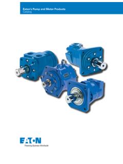
10 Casing Wear rings act as the seal between the casing and the impeller. Centrifugal pumps : Basics Concepts of Operation , Maintenance, and Troubleshooting, Part I. By: Mukesh Sahdev, Associate Content Writer Presented at The Chemical Engineers' Resource Page, Figure : Solid Casing Suction and Discharge Nozzle The suction and discharge nozzles are part of the casings itself. They commonly have the following configurations. 1. End suction/Top discharge (Figure ) - The suction nozzle is located at the end of, and concentric to, the shaft while the discharge nozzle is located at the top of the case perpendicular to the shaft. This pump is always of an overhung type and typically has lower NPSHr because the liquid feeds directly into the impeller eye. 2. Top suction Top discharge nozzle (Figure ) -The suction and discharge nozzles are located at the top of the case perpendicular to the shaft. This pump can either be an overhung type or between-bearing type but is always a radially split case pump.