Transcription of CF 500, CF 600 Circuit Diagrams
1 Table of Contents 1-1. CF 500, CF 600 Circuit Diagrams Table of Contents .. 1-1 Front Wipers and Washers .. 81-1. Introduction .. 3-1 Headlamps .. 85-1. Symbols .. 4-1 Fog Lamps .. 86-1. Connector Repair Procedures .. 5-1 Interior Lamps .. 89-1. Wiring Harness Overview .. 9-1 Turn Signal/Stop/Hazard Lamps .. 90-1. Grounds .. 10-1 Parking, Rear and License Lamps .. 92-1. fuse and Relay information .. 11-1 Reversing Lamps .. 93-1. Charging System .. 12-1 Trailer Adapter .. 95-1. Power Distribution .. 13-1 Daytime Running Lamps .. 97-1. Module Communications Network .. 14-1 Power Windows .. 100-1. Starting System .. 20-1 Power Door Locks .. 110-1. Electronic Engine Controls .. 23-1 Remote Keyless Entry and Alarm.
2 117-1. Transmission Controls .. 29-1 Audio System .. 130-1. Speed Control .. 31-1 Customer Access .. 140-1. Vehicle Dynamic Systems .. 42-1 Component Testing .. 149-1. Horn/Cigar Lighter .. 44-1 Connector Views .. 150-1. Fuel Tank Selector .. 49-1 Component Location Views .. 151-1. Manual Climate Control System .. 54-1 Component Location Charts .. 152-1. Instrument Cluster .. 60-1 Vehicle Repair Location Charts .. 160-1. Cluster and Panel Illumination .. 71-1. NOTE: The descriptions and specifications contained in this manual were in effect at the time this manual was approved for printing. International Truck and Engine Corporation reserves the right to change specifications or design without notice and without incurring any obligation.
3 S08311. 3-1 Introduction Note Central Junc- Hot in run tion Box (CJB). (14A067). All wiring connections between components are shown exactly as they exist 13 4. in the vehicles. It is important to realize, however, that no attempt has been 5A. made on the schematic to represent components and wiring as they 31 C270a 1. physically appear on the vehicle. For example, a 4-foot length of wire is 1405 LB/BK. treated no differently in a schematic from one which is only a few inches See page long. Furthermore, to aid in understanding electrical (electronic) operation, 13 8 6. wiring inside complicated components has been simplified. 11 C220a Instrument cluster (10849). 1) Traction control 5.
4 12 12) ABS. Complete Circuit Operation 1 62 3. 4 16. Each Circuit is shown completely and independently in one cell. Other C220a Data Link Con- nector (DLC). components which are connected to the Circuit may not be shown unless 939 VT 603 DG. (14489). they influence the Circuit operation. 4 2 10 C251. 15 27 C1019 See page See page 14 3 14 3. Current Flow (1) 939 VT 603 DG 3 S157 S156. 914 TN/OG 915 PK/LB. Each cell normally starts with the component that powers the Circuit , such 7 15 3 11 C135. as a fuse or the ignition switch. Current flow is shown from the power ABS control source at the top of the page to ground at the bottom of the page. In order to SCP + SCP module (2C219). 151 5.
5 Concentrate on the essential parts, power supply and ground connections are sometimes simplified by a dashed line in the schematics. A full representation of the power supply of a fuse or the power distribution from 8. a fuse to various components is given in cell 13 Power Distribution . Full 530 LG/YE. representation of the ground connections are shown in cell 10 Grounds . S200. 2 7. 530 LG/YE. Switch Positions (2) G104. Within the schematic, all switches, sensors and relays are shown at rest . (as if the Ignition Switch were OFF). Splices (3). A dashed line indicates that the splice is not shown completely. A reference is given to the page where the splice appears in full. It is also listed in the Index.
6 Introduction 3-2. Component Referencing (4). Each component on a schematic has a reference to the component location view or the page where it is shown completely. It is located to the right of each component. Component Names, Notes and Base Part Numbers (5). Component names are placed on the right hand side of each component. Any notes that describe switch positions or operating conditions follow the name. Descriptions of the internals of the component are also included here. The page where the component appears in full is listed in the Index. The base part number for a component is listed in parentheses next to or under a component. These part numbers will appear any place the component name appears in the publication.
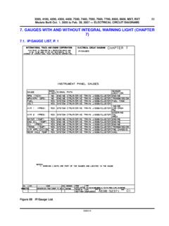
7 Internal Name and Function Identification Numbers (6). Some components on each page have internal symbols with an identification number located to the right. You can identify the internal symbol or function by finding the corresponding number under the component name. Circuit Function Identifiers (7). Some components without internal schematics use symbols or text to describe the function of a Circuit in a system. 3-3 Introduction fuse and Relay information Cell 11 fuse and Relay information contains a view of the fuse -/relay box in which all fuses and relays are identified. fuse and Relay Numbering and Naming fuse and relay numbering and naming follow the indication of the fuse panel cover.
8 In addition, a prefix precedes the fuse number to facilitate finding the fuse in the Component Location Charts, F1. precedes Power Distribution Center fuses, and F2. precedes Central Junction Box fuses. Power Distribution Battery S130. Fusible Link A. 1) 12 gauge Cell 13 Power Distribution shows the current feed Circuit . The current 2) gray path is shown from the battery to the ignition switch and to all fuses. It also S131. shows the circuits protected by each fuse . The Circuit is traced from the fuse Power 57 BK. to the component. All details (wires, splices, connectors) between the fuse 10A. 20A. Distributi on Center and the first component are shown. G1002. (PDC). Power Hot at all times Hot at all times Distributio n Center (PDC).
9 30A 20A. 932 RD 932 RD 196 DB/OG. 1 C1041 1 C1021 7 C220. Headlamp, Headlamp, Instrument right left cluster 85 1 85 1 60 1. Introduction 3-4. Ground Distribution Headlamp, Fog lamp, Fog lamp, right (13008) right front front left Cell 10 Grounds contains the schematics that show the complete details 85 2 (15200). 86 1. (15200). 86 1. 2 C1041 1 C162 1 C152. for each ground connection or main ground splice. This is useful in diagnosing a problem affecting several components at once (poor ground 57 BK 57 BK 57 BK. connection or ground splice). All details (wires, splices, connectors). between the ground point and the components are shown. These ground connection details are shown here in order to keep the individual cell schematics as uncluttered as possible.
10 Side lamp, left Headlamp, front (13411) left (13008). 92 1 85 2. 2 C1127 2 C1021. 57 BK 57 BK. S102. Side lamp, right front (13411). 92 1. 2 C1126. 57 BK 57 BK. G100. 151 3. 3-5 Introduction Component and Connector information Cell 152 Component Location Charts helps the user find where the C150 (BK). various items depicted on the schematic can physically be found on the 12A581. vehicle. A brief written description of the location is given, along with a Wheel speed sen- reference to the component location views. sor, left front (2C205). 2 1. Cell 151 Component Location Views show the components and their connecting wires as they can be found on the vehicle. Cell 150 Connector Views show the views of the pins and/or cavities of FEMALE.