Transcription of CH01 Standard Methods and Practises - EAA 65
1 Chap. 1 Standard Methods and Practises Metal Surface Preparation .. 3. Drilling Holes .. 3. Standard Torque Table [Inch Pounds] *.. 4. Fine Thread Series Coarse Thread 4. Bolt 4. Bolt 6. AN3-AN20 Hex Head Bolt 7. Table 1 - Bolts .. 7. Table 2 - Screws .. 8. Table 3 - Clearance Drill Sizes for AN Bolts, Screws and Cotter 9. 9. AN310 CASTELLATED NUT .. 9. AN315 PLAIN NUT .. 10. AN316 CHECK NUT .. 10. AN365 SELF-LOCKING 11. 11. Plastic 12. 12. Deburring .. 12. 13. Inside Corners and Bend Radii .. 13. Edge 15. Riveting .. 15. Rivet Chart .. 16. Aircraft Solid-Shank Rivets .. 17. Riveting Solid 17. Rivet Pitch .. 17. Bucking Bars.
2 20. Rivet Codes and 21. Rivet Head Styles .. 22. MODEL: COMMON 17/08/2007 Page 1. 1997-2006 Murphy Aircraft Mfg. Ltd. All rights reserved Chap. 1 Standard Methods and Practises Universal Head 23. Countersunk Rivets .. 23. Dimpling .. 24. Inspection of a Rivet 25. Fiberglass Construction .. 27. Making 28. Using 30. Do's and Don'ts in Handling Aluminum Sheets .. 30. Cable Rigging .. 32. Push Pull Tube Fabrication .. 33. Reamers .. 34. Metal Working Glossary of Terms .. 35. Turnbuckle Assemblies .. 36. Safety Methods for 36. Double Wrap Method .. 37. Swaged terminal method .. 37. Nut Plates (Floating Anchor Nuts) .. 38. Installing Nut Plates.
3 38. Some Final 39. Work Table 40. Material requirements .. 40. Throughout this manual various styles of bullets will be used to convey information, as a general rule they will be used as follows:- Advisory information. Lists of facts to be adhered to, factual information or consequences. 1) Methods or processes to be followed. a. Sequence of steps within the Methods or Processes to be followed. MODEL: COMMON 17/08/2007 Page 2. 1997-2006 Murphy Aircraft Mfg. Ltd. All rights reserved Chap. 1 Standard Methods and Practises Please read the following information carefully, you will need to refer to it often throughout the building process.
4 It contains information on corrosion protection, drilling, deburring, gusset building etc. Also included is a section on bolt and rivet selection to assist you in areas of the manual where bolt or rivet sizes have not been indicated. Metal Surface Preparation As a protective measure against corrosion, mating metal surfaces should be fully deburred, cleaned with Acetone, and then coated liberally with primer. This provides a seal between the surfaces to prevent corrosion and moisture ingress. It is a good practice to coat the end of the rivet on the inside surface after installation. As an optional measure, the rivets can be dipped in primer prior to installation.
5 This provides protection inside the hole and seals out moisture, be careful to avoid getting excess chromate on the exterior surfaces. Epoxy primer must be mixed in accordance with the manufacturers directions as displayed on the containers. It is advisable to mix only the amount required at the time in a small container for immediate use. However, it is possible to mix larger amounts for reuse but these must be kept in a sealed container and stored in a freezer or refrigerator. Drilling Holes It is good practice to only use a #40 drill to make pilot holes when doing any assembly work. If possible never drill to final hole size until assembly is complete and you are confident to do so.
6 This allows for any movement between parts or adjustment you may need to make which could cause misalignment of the holes during final assembly. Always use a sharp drill bit as: A sharp bit will not wander as easily as a dull one. You can drill faster with a sharp bit. You don't have to push as hard, risking bending flanges etc. Always be careful to drill square to the work surface. Always make sure when drilling through multiple parts or layers that they are clamped together tightly and there is no movement during drilling. Always deburr holes on both sides of each part before final assembly. Always keep work surfaces clean and free from swarf which can scratch and damage panels.
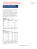
7 MODEL: COMMON 17/08/2007 Page 3. 1997-2006 Murphy Aircraft Mfg. Ltd. All rights reserved Chap. 1 Standard Methods and Practises Standard Torque Table [Inch Pounds] *. The following information is provided for reference when using AN grade hardware. Most of the time torque values are done to feel. However, this table does provide a good guideline. Note: Occasionally bolts, other than a Standard bolt will be specified in the manual. These have been specially selected to provide the necessary strength for the particular connection, and where a Standard bolt would not be strong enough. It is important that the bolts specified are used where instructed.
8 Fine Thread Series Coarse Thread Series Bolt Size Standard Nuts Shear Nuts Bolt Size Standard Nuts Shear Nuts (MS20365, AN310, (MS20364, AN320, (MS20365, AN310, (MS20364, AN320, AN315) AN316, AN23-31) AN315) AN316, AN23-31). 10-32 20-25 12-15 8-32 12-15 7-9. 1/4-28 50-70 30-40 10-24 20-25 12-15. 5/16-24 100-140 60-85 1/4-20 40-50 25-30. 3/8-24 160-190 95-110 5/16-18 80-90 48-55. 7/16-20 450-500 270-300 3/8-16 160-185 95-110. 1/2-20 480-690 290-410 7/16-14 235-255 140-155. 9/16-18 800-1000 480-600 1/2-13 400-480 240-290. 5/8-18 1100-1300 660-740 9/16-12 500-700 300-420. * The above calculations were obtained from the Standard Aircraft Handbook.
9 Bolt Lengths Throughout the building process there will be instances where bolts are used to fasten parts or materials together. Unless specified, it will be builder who determines the correct length of the bolt to be used. The Rule of Thumb for determining bolt length is that the bolt must be long enough to pass through the parts or material being fastened together so that: The threaded part of the bolt is never in shear [ no threads are allowed inside hole]. No more than three and no less than one thread must be showing when the nut is attached and tightened to the correct torque value. Although it is not mandatory to use washers on steel or aluminum parts it is a good practise to use one under the nut.
10 MODEL: COMMON 17/08/2007 Page 4. 1997-2006 Murphy Aircraft Mfg. Ltd. All rights reserved Chap. 1 Standard Methods and Practises More precise determinations of Grip Length are found in a number of books including the Standard Aircraft Worker's Manual. MODEL: COMMON 17/08/2007 Page 5. 1997-2006 Murphy Aircraft Mfg. Ltd. All rights reserved Chap. 1 Standard Methods and Practises Bolt Identification AN bolts may be obtained in the following materials:- [-] Steel, cadmium plated C Corrosion resisting steel DD Aluminum alloy The coding symbols shown in the bolt identification number follow the basic AN [Dash] number and identify the material required.