Transcription of Ch4. LLC Resonant Converter
1 Bo Yang Chapter 4. LLC Resonant Converter 94 Chapter 4 LLC Resonant Converter introduction In previous chapters, the trends and technical challenges for front end DC/DC Converter were discussed. High power density, high efficiency and high power are the major driving force for this application. Hold up time requirement poses big penalty to the system performance. Two methods were proposed in chapter 2 to solve this problem and improve the efficiency. Range winding solution could improve the performance at high input voltage significantly, but with extra devices, windings and control circuit. Asymmetrical winding solution provides a simpler solution, but could only apply to asymmetrical half bridge topology. Also it introduced other problems like discontinuous output current and unbalanced stress.
2 To catch up with and move ahead of the trend, higher switching frequency, higher efficiency and advanced packaging are the paths we are taking now. Within all these issues, a topology capable of higher switching frequency with higher efficiency is the key to achieve the goal. With the techniques proposed in chapter 2, the performance at normal operation could be improved. But none of these methods dealt with the switching Bo Yang Chapter 4. LLC Resonant Converter 95loss problem of PWM Converter . Even with Zero Voltage Switching technique, the turn on loss could be minimized; turn off loss still limits the capability of the Converter to operate at higher switching frequency. Resonant Converter , which were been investigated intensively in the 80's [B1]-[B7], can achieve very low switching loss thus enable Resonant topologies to operate at high switching frequency.
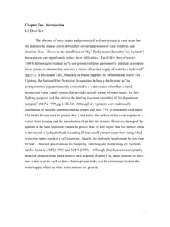
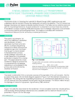
3 In Resonant topologies, Series Resonant Converter (SRC), Parallel Resonant Converter (PRC) and Series Parallel Resonant Converter (SPRC, also called LCC Resonant Converter ) are the three most popular topologies. The analysis and design of these topologies have been studied thoroughly. In next part, these three topologies will be investigated for front-end application. Three traditional Resonant topologies In this part, these three topologies will be evaluated for front end DC/DC application. The major goal is to evaluate the performance of the Converter with wide input range. For each topology, the switching frequency is designed at around 200kHz. Series Resonant Converter The circuit diagram of a half bridge Series Resonant Converter is shown in Figure [B8]-[B13]. The DC characteristic of SRC is shown in Figure The Resonant inductor Lr and Resonant capacitor Cr are in series.
4 They form a series Bo Yang Chapter 4. LLC Resonant Converter 96resonant tank. The Resonant tank will then in series with the load. From this configuration, the Resonant tank and the load act as a voltage divider. By changing the frequency of input voltage Va, the impedance of Resonant tank will change. This impedance will divide the input voltage with load. Since it is a voltage divider, the DC gain of SRC is always lower than 1. At Resonant frequency, the impedance of series Resonant tank will be very small; all the input voltage will drop on the load. So for series Resonant Converter , the maximum gain happens at Resonant frequency. Figure half Bridge Series Resonant Converter For front end DC/DC application, a SRC is designed to meet the specifications with following parameters: Transformer turns ratio: 5:2, Resonant inductance: 37uH, Resonant capacitance: 17nF.
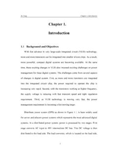
5 Bo Yang Chapter 4. LLC Resonant Converter 97 Figure DC characteristic and operating region of SRC Figure Simulation waveforms of SRC With above parameters, the range of Q is from 6 (Full load) to 0 (No load). With above design, the operating region of the Converter is shown in Figure as shaded area. Simulation waveform is shown in Figure From the operating region graph and simulation waveforms, several things could be observed: Bo Yang Chapter 4. LLC Resonant Converter 98 Operating region is on the right side of Resonant frequency fr. This is because of zero voltage switching (ZVS) is preferred for this Converter .
6 When switching frequency is lower than Resonant frequency, the Converter will work under zero current switching (ZCS) condition. In fact, the rule is when the DC gain slope is negative; the Converter is working under zero voltage switching condition. When the DC gain slop is positive, the Converter will work under zero current switching condition. For power MOSFET, zero voltage switching is preferred. It can be seen from the operating region that at light load, the switching frequency need to increase to very high to keep output voltage regulated. This is a big problem for SRC. To regulate the output voltage at light load, some other control method has to be added. At 300V input, the Converter is working close to Resonant frequency. As input voltage increases, the Converter is working at higher frequency away from Resonant frequency. As frequency increases, the impedance of the Resonant tank is increased.
7 This means more and more energy is circulating in the Resonant tank instead of transferred to output. From simulation waveforms, at 300V input, the circulating energy is much smaller than 400V input situation. Here the circulating energy is defined as the energy send back to input source in each switching cycle. The more energy is sending back to the source during each switching cycle, the higher the energy needs to be processed by the semiconductors, the higher the conduction loss. Bo Yang Chapter 4. LLC Resonant Converter 99 Also from the MOSFET current we can see that the turn off current is much smaller in 300V input. When input voltage increases to 400V, the turn off current is more than 10A, which is around the same level as PWM Converter .
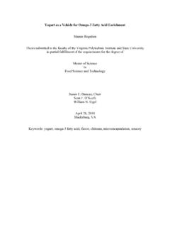
8 With above analysis, we can see that SRC is not a good candidate for front end DC/DC Converter . The major problems are: light load regulation, high circulating energy and turn off current at high input voltage condition. Parallel Resonant Converter The schematic of parallel Resonant Converter is shown in Figure [B14]-[B17]. Its DC characteristic is shown in Figure For parallel Resonant Converter , the Resonant tank is still in series. It is called parallel Resonant Converter because in this case the load is in parallel with the Resonant capacitor. More accurately, this Converter should be called series Resonant Converter with parallel load. Since transformer primary side is a capacitor, an inductor is added on the secondary side to math the impedance. Figure half bridge parallel Resonant Converter Bo Yang Chapter 4.
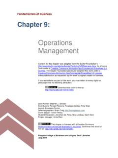
9 LLC Resonant Converter 100 Figure DC characteristic and operating region of PRC The parameters of parallel Resonant Converter designed for front end DC/DC application are: Transformer turns ratio: 9:1, Resonant inductance: 58uH, Resonant capacitance: With above parameters, the range of Q for this Converter is 3 (Full load) to (No load). The operating region of PRC is shown in Figure as shaded area. Simulation waveform is shown in Figure From the operating region graph and simulation waveforms, several things could be observed: Bo Yang Chapter 4. LLC Resonant Converter 101 Figure Simulation waveforms of PRC 1. Similar to SRC, the operating region is also designed on the right hand side of Resonant frequency to achieve Zero Voltage Switching.
10 Compare with SRC, the operating region is much smaller. At light load, the frequency doesn't need to change too much to keep output voltage regulated. So light load regulation problem doesn't exist in PRC. Same as SRC for PRC, the Converter is working close to Resonant frequency at 300V. At high input voltage, the Converter is working at higher frequency far away from Resonant frequency. From simulation waveforms, at 300V input, the circulating energy is smaller than 400V input situation. Compare with SRC, it can be seen that for PRC, the circulating energy is much larger. Also from the MOSFET current we can see that the turn off current is much smaller in 300V input. When input voltage Bo Yang Chapter 4. LLC Resonant Converter 102increases to 400V, the turn off current is more than 15A, which is even higher than PWM Converter .