Transcription of CHAIN-LINK FENCE AND GATE - Main Line Fence
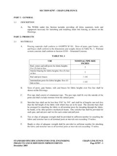
1 chain -LINKFENCE AND GATEINSTALLATION INSTRUCTIONSF encing Without BoundariesTM1 Terminal Post Cap6 FENCE Tie11 Tension Bar2 Rail End7 gate Frame Hinge12 Top Rail3 Rail End Band8 gate Post Hinge13 Line Post4 Tension Band9 gate Fork Latch14 Bottom Tension Wire5 Line Post Top10 Terminal Post15 Tension Wire ClipBEFORE YOU START, IT S IMPORTANT TO CHECK ..PARTS LIST1..That FENCE footings do not exceed legally established property lines. If uncertain, refer to realestate agent s line plot or consult a professional ..Local codes for specifications regarding frontage locations, allowable FENCE heights, etc. Apermit may be ..With local utility companies for locations of underground cables or FENCE & GATEI nstallation InstructionsCHAIN- link FENCE AND GATE2 PARTS DESCRIPTION QUANTITY TO USE / BUYCHAIN- link FENCE & GATEI nstallation InstructionsChain-LinkFabricTop RailSleeveTop Rail(plain orswedged end)Line Post(intermediate post)Terminal Post(end, corner andgate posts)Same linear footage of fenceless gate openings1 for each length of plain end toprail.
2 Not needed for swedged endtop linear footage as fencefabricDivide the total footage of yourfence (less gate openings) by 10and subtract 1. Subtract 1additional line post for eachcorner post used. Space lineposts equidistant at intervals notexceeding 10 required (2 for each gate )Tension Bar1 for each end post1 for each gate post2 for each corner post10131211 TOOLS YOU WILL FIND USEFULS ingleSwing GateDoubleSwing GateTerminal PostCapLine Post TopRail EndRail End BandTension BandGate PostHingeGate FrameHingeGate ForkLatchFence Tie5/16" x 1-1/4"Carriage Bolt3/8" x 2"Carriage Bolt3/8" x 3"Carriage BoltBottomTension WireTension Wire ClipConcrete Mix1 for each gate frame hingeApproximately two 60-lb.
3 Sacksper post holeSame linear footage of fenceless gate openings1 for every 24" of tension wire1 for each gate post hinge1 for each rail end band1 for each tension band1 for every 24" of top rail and 1for every 12" of line posts1 for each single swing gate2 for single swing gate4 for double swing gate2 for single swing gate4 for double swing gateFor each end post, use 3 for: 3',42" or 4'; use 4 each for 5', anduse 5 each for 6'. Same for gateposts. Double the quantity forcorner for each rail end1 for each end post1 for each gate post2 for each corner post1 for each line post1 for each terminal postIndividual fittings as indicatedbelowString or Chalk Line and Stakes Tape Measure Post Hole DiggerWheelbarrow, Shovel and Hoe to mix and transport concrete Carpenter s Level1/2" and 9/16" Wrench or Crescent Wrench Hacksaw or Pipe CutterFence Stretcher Pliers Tension Wire Clip (Hog Ring)
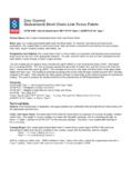
4 PliersIndividualfittings asindicated below15234879614153 CHAIN-LINK FENCE & GATEI nstallation InstructionsPOST SPACING CHARTDISTANCEBETWEENTERMINAL POSTSDISTANCEBETWEENLINE POSTS30'10'31'7' 9"32'8'33'8' 3"34'8' 6"35'8' 9"36'9'37'9' 3"38'9' 6"39'9' 9"40'10'41'8' 2"42'8' 5"43'8' 6"44'8' 9"45'9'46'9' 2"47'9' 5"48'9' 7"49'9' 9"50'10'51'8' 6"52'8' 8"53'8' 10"54'9'55'9' 2"56'9' 4"57'9' 6"58'9' 8"59'9' 10"60'10'61'8' 8"62'8' 10"63'9'64'9' 1"65'9' 3"66'9' 5"67'9' 7"68'9' 8"69'9' 10"70'10'71'8' 10"72'9'73'9' 1"74'9' 3"75'9' 4"76'9' 6"77'9' 7"78'9' 9"79'9' 10"80'10'81'9'82'9' 1"83'9' 3"84'9' 4"85'9' 5"86'9' 7"87'9' 8"88'9' 9"89'9' 10"90'10'91'9' 1"92'9' 2"93'9' 4"94'9' 5"95'9' 6"96'9' 7"97'9' 8"98'9' 9"99'9' 10"100'10'IN THE SPACE PROVIDED BELOW, MAKE A SKETCH OFYOUR FENCE LAYOUT4 PREPARE FENCE LAYOUT1 CHAIN-LINK FENCE & GATEI nstallation InstructionsStandardopening widths:Single Swing 36", 39",42" and 48"Double Swing 10 12 stock sizes may varybased on 1 Locate your property s boundary is recommended that all posts be setapproximately 4" inside the property line sothat concrete footings do not encroach ontoany adjoining 2 Measure the overall length of your plannedfence to determine how many feet of CHAIN-LINK fabric and top rail will be required(Fig.)
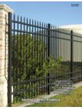
5 1).STEP 3 Mark the location of each terminal post(corner, end, and gate posts are calledterminalposts) with a determining the positions of gateposts remember that clearance for hinges,latches, etc., is included in the listedopening width of the gate . Therefore, if youordered a gate for a 36" opening the postspacing should be exactly 36", inside postface to inside post 1 Line PostCorner PostCornerPostGate PostGate PostDoubleSwing GateSingleSwing GateGate PostGate PostLine PostEnd PostStringString5 SETTING TERMINAL POSTS2 LOCATING AND SETTING LINE POSTS3 CHAIN-LINK FENCE & GATEI nstallation InstructionsFigure 2 Figure 3 Figure 4 STEP 1 Dig terminal post holes approximately 8" in diameter and 30" deep, withsloping sides (Fig.
6 2). The exact diameter and depth will be determined bylocal weather and soil 2 With crayon or chalk, mark the ground line on posts. Height, above levelground, of terminal posts will equal the height of the FENCE fabric plus 2".STEP 3 Center the terminal posts in the holes. Make sure the posts are plumb andset at the correct height. (Crayon mark should be at ground level.)Surround posts with concrete in a continuous pour. Trowel finish aroundposts and slope downward to direct water 2 Measure the distance between terminal posts and refer to Post SpacingChart to determine the distance between line posts. Dig line post holes 6"wide and 18" to 24" deep, with sloping sides (Fig.
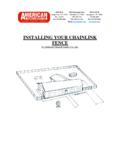
7 4). Center the lineposts in the holes. Make sure the posts are plumb, aligned with the centersof terminal posts, and set at the correct height. Surround posts withconcrete in a continuous pour. Trowel finish around posts and slopedownward to direct water 1 When the terminal post footings havehardened enough to stabilize the posts,stretch a string line taut between terminalposts. The string should be positioned onthe outside face of the posts 4" below thetop (Fig. 3). Height, above level ground,of line posts will equal the height of thefabric minus 2".TerminalPostLine PostStringLine PostTerminalPostCrayonMarkTerminalPost8" FenceFabricHeight2"4"4"30"6"FenceFabricH eight2"18" 24"LinePost6 CHAIN-LINK FENCE & GATEI nstallation InstructionsADDING FITTINGS TO TERMINAL POSTS4 Figure 6 Figure 5 Figure 7 End and gate PostCorner PostTerraced GroundCorner post assembly is usedat point A to allow fabric tofollow terraced contour ofground (Fig.
8 6).Very Uneven GroundCorner post assembly is usedat points A and B whenground rises or drops morethan 15" per 100 linear feet(Fig. 7).STEP 1 After concrete footings have been allowed tosufficiently harden, slip the rail end bands andtension bands onto the terminal posts. (Refer toparts list for the description and quantity of fittingsthat are required for various post types andheights.)The long flat surface of the tension bandshould face toward the outside of the FENCE (Fig 5).NOTE: Take care not to spread or distort 2 Apply all terminal post EndBandTerminalPost CapTensionBandsRail EndBand forTension Wire7 CHAIN-LINK FENCE & GATEI nstallation InstructionsINSTALLING TOP RAILS5 ADDING TENSION WIRE (Optional)6 STEP 2 Insert one length of top rail through the line post top closest to aterminal post.
9 Slip rail end onto the end of the top rail and attachit to a terminal post by using a rail end band. Secure by using a5/16" x 1-1/4" carriage bolt with the head to the outside of thefence (Fig. 9).STEP 1 Place line post top on the top of each line post. The off-set roundside should be toward the outside of the FENCE (Fig. 8).Off-setRound SideLine PostTo pRail EndBandTop RailRail EndSTEP 3 Continue by forcing lengths of swedge end top rail togetherthrough the line post tops. (If swedge end top rail is not used, joinlengths together with top rail sleeves.) (Fig. 10)STEP 4 Upon reaching the next terminal post, measure carefully and cutthe top rail to fit tightly between the last length of top rail and therail end.
10 Fasten rail end to rail end band on the terminal in place with a 5/16" x 1-1/4" carriage bolt (Fig. 11).Wrap tension wire once around bottom rail end band carriagebolt. Using pliers, twist several times to secure (Fig. 12).Tension wire should run along the same side of the posts as thefabric. Apply tension wire clips no more than 24" apart, or asneeded for securing the wire to the CHAIN-LINK EndBandTensionWireTop RailSleeveFigure 10 Figure 8 Figure 9 Figure 11 Figure 128 CHAIN-LINK FENCE & GATEI nstallation InstructionsHANGING FENCE FABRIC7 Figure 13 Figure 14 Figure 15 Figure 16 STEP 1 Starting at a terminal post, unroll chain -linkfabric on the ground along the outside of thefence line to the next terminal post.