Transcription of Chapter 10 Aircraft Instrument Systems
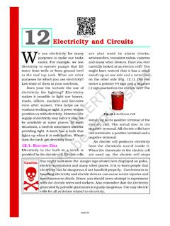
1 10-1 IntroductionSince the beginning of manned flight, it has been recognized that supplying the pilot with information about the Aircraft and its operation could be useful and lead to safer flight. The Wright Brothers had very few instruments on their Wright Flyer, but they did have an engine tachometer, an anemometer (wind meter), and a stop watch. They were obviously concerned about the Aircraft s engine and the progress of their flight. From that simple beginning, a wide variety of instruments have been developed to inform flight crews of different parameters. Instrument Systems now exist to provide information on the condition of the Aircraft , engine, components, the Aircraft s attitude in the sky, weather, cabin environment, navigation, and communication.
2 Figure 10-1 shows various Instrument panels from the Wright Flyer to a modern jet airliner. Aircraft Instrument SystemsChapter 1010-2 Figure 10-2. A conventional Instrument panel of the C-5A Galaxy (top) and the glass cockpit of the C-5B Galaxy (bottom).Figure 10-1. From top to bottom: instruments of the Wright Flyer, instruments on a World War I era Aircraft , a late 1950s/early 1960s Boeing 707 airliner cockpit, and an Airbus A380 glass ability to capture and convey all of the information a pilot may want, in an accurate, easily understood manner, has been a challenge throughout the history of aviation. As the range of desired information has grown, so too have the size and complexity of modern Aircraft , thus expanding even further the need to inform the flight crew without sensory overload or overcluttering the cockpit.
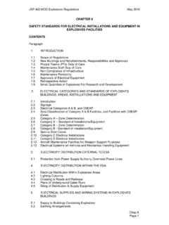
3 As a result, the old flat panel in the front of the cockpit with various individual instruments attached to it has evolved into a sophisticated computer-controlled digital interface with flat-panel display screens and prioritized messaging. A visual comparison between a conventional cockpit and a glass cockpit is shown in Figure 10-2. There are usually two parts to any Instrument or Instrument system. One part senses the situation and the other part displays it. In analog instruments, both of these functions often take place in a single unit or Instrument (case). These are called direct-sensing instruments. Remote-sensing requires the information to be sensed, or captured, and then sent to a separate display unit in the cockpit.
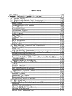
4 Both analog and digital instruments make use of this method. [Figure 10-3]10-3 Figure 10-3. There are two parts to any Instrument system the sensing mechanism and the display + IndicationSensorIndicationDirect-sensing Instrument systemRemote-sensing Instrument systemFigure 10-4. The basic T arrangement of analog flight instruments. At the bottom of the T is a heading indicator that functions as a compass but is driven by a gyroscope and not subject to the oscillations common to magnetic direction relaying of important bits of information can be done in various ways. electricity is often used by way of wires that carry sensor information into the cockpit. Sometimes pneumatic lines are used. In complex, modern Aircraft , this can lead to an enormous amount of tubing and wiring terminating behind the Instrument display panel.
5 More efficient information transfer has been accomplished via the use of digital data buses. Essentially, these are wires that share message carrying for many instruments by digitally encoding the signal for each. This reduces the number of wires and weight required to transfer remotely sensed information for the pilot s use. Flat-panel computer display screens that can be controlled to show only the information desired are also lighter in weight than the numerous individual gauges it would take to display the same information simultaneously. An added bonus is the increased reliability inherent in these solid-state is the job of the Aircraft technician to understand and maintain all Aircraft , including these various Instrument Systems .
6 Accordingly, in this Chapter , discussions begin with analog instruments and refer to modern digital instrumentation when InstrumentsThere are three basic kinds of instruments classified by the job they perform: flight instruments, engine instruments, and navigation instruments. There are also miscellaneous gauges and indicators that provide information that do not fall into these classifications, especially on large complex Aircraft . Flight control position, cabin environmental Systems , electrical power, and auxiliary power units (APUs), for example, are all monitored and controlled from the cockpit via the use of instruments Systems . All may be regarded as position/condition instruments since they usually report the position of a certain moveable component on the Aircraft , or the condition of various Aircraft components or Systems not included in the first three groups.
7 Flight InstrumentsThe instruments used in controlling the Aircraft s flight attitude are known as the flight instruments. There are basic flight instruments, such as the altimeter that displays Aircraft altitude; the airspeed indicator; and the magnetic direction indicator, a form of compass. Additionally, an artificial horizon, turn coordinator, and vertical speed indicator are flight instruments present in most Aircraft . Much variation exists for these instruments, which is explained throughout this Chapter . Over the years, flight instruments have come to be situated similarly on the Instrument panels in most Aircraft . This basic T arrangement for flight instruments is shown in Figure 10-4. The top center position directly in front of the pilot and copilot is the basic display position for the artificial horizon even in modern glass cockpits (those with solid-state, flat-panel screen indicating Systems ).
8 Original analog flight instruments are operated by air pressure and the use of gyroscopes. This avoids the use of electricity , which could put the pilot in a dangerous situation if the Aircraft lost electrical power. Development of sensing and display techniques, combined with advanced Aircraft electrical Systems , has made it possible for reliable primary and secondary Instrument Systems that are electrically operated. Nonetheless, often a pneumatic altimeter, a gyro artificial horizon, and a magnetic direction indicator are retained somewhere in the Instrument panel for redundancy. [Figure 10-5]Engine InstrumentsEngine instruments are those designed to measure operating parameters of the Aircraft s engine(s). These are usually quantity, pressure, and temperature indications.
9 They also include measuring engine speed(s). The most common engine instruments are the fuel and oil quantity and pressure gauges, tachometers, and temperature gauges. Figure 10-6 contains various engine instruments found on reciprocating and turbine-powered 10-7. An engine instrumentation located in the middle of the Instrument panel is shared by the pilot and co-pilot. Figure 10-5. This electrically operated flat screen display Instrument panel, or glass cockpit, retains an analog airspeed indicator, a gyroscope-driven artificial horizon, and an analog altimeter as a backup should electric power be lost, or a display unit 5537 IDNT LCL23:00:34 VOR 1 270 2 1 1 2 4300 4200 4100 3900 3900 3800 4300 20 804000 4000 130 120 110 90 80 70 1 100 9 TAS 100KT OAT 7 C ALERTS NAV1 COM2 WPT _ _ _ _ _ _ DIS _ _.
10 _ NM DTK _ _ _ TRK 360 N-S E-W VOLTS COM2 WPT _ _ _ _ _ _ DIS _ _ ._ NM DTK _ _ _ TRK 360 MAP - NAVIGATION MAP Figure 10-6. Common engine instruments. Note: For example purposes only. Some Aircraft may not have these instruments or may be equipped with enginesOil pressure Oil pressureOil temperature Exhaust gas temperature (EGT)Cylinder head temperature (CHT) Turbine inlet temperature (TIT) or turbine gas temperature (TGT)Manifold pressure Engine pressure ratio (EPR)Fuel quantity Fuel quantityFuel pressure Fuel pressure Fuel flowTachometer Tachometer (percent calibrated) N1 and N2 compressor speedsCarburetor temperature Torquemeter (on turboprop and turboshaft engines)Turbine enginesEngine instrumentation is often displayed in the center of the cockpit where it is easily visible to the pilot and copilot.


![Electricity Regulation Act [No. 4 of 2006] - Energy](/cache/preview/6/a/5/5/a/0/d/5/thumb-6a55a0d556b9c34cf91d66ae31989ed3.jpg)