Transcription of CHAPTER 10 DIGITAL RECORDING STANDARD …
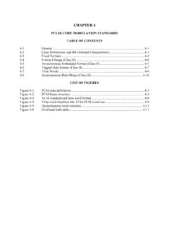
1 RCC Document 106-07, Telemetry STANDARD , CHAPTER 10, September 2007 CHAPTER 10 ChangeDIGITAL RECORDING STANDARD table OF CONTENTS Paragraph Subject Page LIST OF FIGURES .. ii LIST OF TABLES .. iv General .. 10-1 10-4 Operational Requirements .. 10-8 Data Download and Electrical Interface .. 10-13 Interface File Structure Definition .. 10-17 Data Format Definition .. 10-26 Recorder Control and Status .. 10-120 10-125 IEEE 1394B Interface to Recorder Media .. 10-127 Ground Based Recorders.. 10-138 Data Interoperability .. 10-141 Telemetry STANDARD RCC Document 106-07, CHAPTER 10, September 2007 LIST OF FIGURES Figure 10-1. Functional layout of STANDARD .. 10-3 Figure 10-2. UDP Transfer Header for non-segmented 10-12 Figure 10-3.
2 UDP Transfer Header for segmented data.. 10-12 Figure 10-4. General UDP Network Broadcast (full packet).. 10-13 Figure 10-5. General UDP Network Broadcast (segmented packet).. 10-13 Figure 10-6. Directory structure.. 10-21 Figure 10-7. Directory block.. 10-21 Figure 10-8. Data RECORDING 10-27 Figure 10-9. General packet 10-28 Figure 10-10. A 32-bit packet format layout.. 10-29 Figure 10-11. Packet trailer for 32 bit data 10-30 Figure 10-12. Packet trailer for 8-bit data checksum.. 10-30 Figure 10-13. General PCM data packet, format 10-38 Figure 10-14. PCM packet channel specific data format.. 10-39 Figure 10-15. PCM Data unpacked mode sample packet.. 10-42 Figure 10-16. PCM Data packed mode sample packet.. 10-43 Figure 10-17. PCM Data Throughput Mode sample packet.. 10-44 Figure 10-18. 32-bit Alignment Mode example, 16-bit data words (32 bit word addressing).. 10-44 Figure 10-19. 32-bit Alignment Mode example, 16-bit data words (16-bit word addressing).. 10-45 Figure 10-20.
3 PCM Intra-packet header.. 10-45 Figure 10-21. General time data packet, format 1.. 10-47 Figure 10-22. Time Packet channel specific data format.. 10-47 Figure 10-23. Time data - packet format, day format.. 10-48 Figure 10-24. Time data - packet format, day, month, and year 10-48 Figure 10-25. MIL-STD-1553 Packet channel specific data format.. 10-49 Figure 10-26. MIL-STD-1553 data packet, format 1.. 10-50 Figure 10-27. MIL-STD-1553 intra-packet data header.. 10-51 Figure 10-28. Block status word format.. 10-51 Figure 10-29. Gap Times word format.. 10-52 Figure 10-30. MIL-STD-1553 data packet, format 1.. 10-54 Figure 10-31. 16PP194 message transaction.. 10-55 Figure 10-32. MIL-STD-1553 16PP194 packet channel specific data format.. 10-55 Figure 10-33. MIL-STD-1553 16PP194 data packet.. 10-56 Figure 10-34. MIL-STD-1553 16PP194 intra-packet data header format.. 10-57 Figure 10-35. MIL-STD-1553 16PP194 data packet.. 10-58 Figure 10-36. MIL-STD-1553 26-bit 16PP194 word format.. 10-59 Figure 10-37.
4 16PP194 Word Format.. 10-60 Figure 10-38. Generic analog data packet, format 1.. 10-61 Figure 10-39. Analog data packet format.. 10-62 Figure 10-40. Analog data packet - unpacked mode, msb padding.. 10-66 Figure 10-41. Analog data packet - unpacked mode, lsb padding.. 10-67 Figure 10-42. Analog data packet packed mode packet.. 10-68 Figure 10-43. General discrete data packet, format 10-68 ii Telemetry STANDARD RCC Document 106-07, CHAPTER 10, September 2007 Figure 10-44. Discrete packet channel data word 10-69 Figure 10-45. Discrete data 10-69 Figure 10-46. Discrete event intra-packet 10-70 Figure 10-47. Discrete data packet format.. 10-70 Figure 10-48. General computer generated data packet format.. 10-71 Figure 10-49. Computer generated format 0 channel specific data word format.. 10-71 Figure 10-50. Computer generated format 1 channel specific data word format.. 10-72 Figure 10-51. Computer generated format 2 channel specific data word.. 10-73 Figure 10-52. Events RECORDING period.
5 10-74 Figure 10-53. RECORDING event intra-packet header.. 10-76 Figure 10-54. General RECORDING event packet 10-76 Figure 10-55. RECORDING event entry layout.. 10-77 Figure 10-56. Format showing root index 10-79 Figure 10-57. Channel specific data word format.. 10-79 Figure 10-58. RECORDING index intra-packet header.. 10-80 Figure 10-59. General RECORDING root index 10-81 Figure 10-60. RECORDING root index entry layout.. 10-82 Figure 10-61. General RECORDING node index packet.. 10-82 Figure 10-62. RECORDING node index entry layout.. 10-83 Figure 10-63. ARINC-429 data packet format.. 10-84 Figure 10-64. ARINC-429 packet channel specific data word format.. 10-84 Figure 10-65. Intra-packet data header format.. 10-85 Figure 10-66. Message data packet 10-86 Figure 10-67. Complete message channel specific data word format.. 10-87 Figure 10-68. Segmented message channel specific data word 10-87 Figure 10-69. Message data intra-packet header.. 10-88 Figure 10-70. Intra-packet data header format.
6 10-88 Figure 10-71. General MPEG-2 video packet, format 0.. 10-89 Figure 10-72. Video packet channel specific data word format.. 10-90 Figure 10-73. Intra-packet header.. 10-92 Figure 10-74. Format 0 MPEG-2 video frame sync and word format (Example is 16 bit aligned).. 10-93 Figure 10-75. Format 0 MPEG-2 Video Data Packet (Example is 16 Bit Aligned).. 10-93 Figure 10-76. General MPEG-2 video packet, format 1.. 10-94 Figure 10-77. MPEG-2 channel specific data word 10-94 Figure 10-78. Intra-packet header.. 10-97 Figure 10-79. General video packet, format 2.. 10-98 Figure 10-80. channel specific data word 10-98 Figure 10-81. Intra-packet header.. 10-101 Figure 10-82. Image packet, format 0.. 10-102 Figure 10-83. Image packet channel specific data word 10-102 Figure 10-84. Image data intra-packet header, format 0.. 10-103 Figure 10-85. Still Imagery packet, format 1.. 10-104 Figure 10-86. Still Imagery packet channel specific data word 10-104 Figure 10-87. Still Imagery intra-packet 10-105 iii Telemetry STANDARD RCC Document 106-07, CHAPTER 10, September 2007 Figure 10-88.
7 UART data packet 10-106 Figure 10-89. UART packet channel specific data word 10-107 Figure 10-90. UART data intra-packet header.. 10-107 Figure 10-91. Intra-packet data header format.. 10-108 Figure 10-92. IEEE-1394 data packet, format 10-108 Figure 10-93. IEEE-1394 channel specific data 10-109 Figure 10-94. IEEE-1394 intra-packet 10-109 Figure 10-95. IEEE-1394 event data word format.. 10-110 Figure 10-96. IEEE-1394 data packet, format 10-112 Figure 10-97. IEEE-1394 channel specific data word format 1.. 10-112 Figure 10-98. IEEE-1394 format 1 intra-packet header.. 10-112 Figure 10-99. Intra-packet data header - message ID word.. 10-113 Figure 10-100. Parallel data packet, format 0.. 10-115 Figure 10-101. Parallel packet channel specific data word format.. 10-115 Figure 10-102. Parallel data, up to 8-bit wide words.. 10-116 Figure 10-103. Parallel data, 9-16 bit wide words.. 10-116 Figure 10-104. Parallel data, (Example: 28-bit wide words).. 10-116 Figure 10-105.
8 DCRsi Scan, 9-auxiliary data byte +4356 bytes.. 10-117 Figure 10-106. Ethernet Data packet format 1.. 10-118 Figure 10-107. Ethernet Data packet format 1 channel specific data word.. 10-119 Figure 10-108. Ethernet Data format 1 intra-packet header.. 10-119 Figure 10-109. Intra-packet frame ID word.. 10-120 Figure 10-110. Required discrete control functions.. 10-123 Figure 10-111. Discrete control and indicator functional diagram.. 10-123 Figure 10-112. Removable media.. 10-128 Figure 10-113. RMM .HEALTH command response.. 10-129 Figure 10-114. Login ORB format.. 10-133 Figure 10-115. Login response format.. 10-134 Figure 10-116. Send command ORB 10-135 Figure 10-117. Send data buffer format.. 10-136 Figure 10-118. Receive command block ORB format (8quadlets).. 10-137 Figure 10-119. Receive data buffer format.. 10-138 LIST OF TABLES table 10-1. Required and Recommended SCSI Commands, Features, and Parameters .. 10-15 table 10-2. Directory Block Format.
9 10-22 table 10-3. Directory Entry 10-23 table 10-4. Prohibited Characters (Hexadecimal Representation) .. 10-25 table 10-5. File Name Examples .. 10-25 table 10-6. Packet 10-31 table 10-7. Data Type Names and 10-35 table 10-8. Units of 10-49 table 10-9. Command Summary .. 10-122 table 10-10. Recorder LED 10-125 iv Telemetry STANDARD RCC Document 106-07, CHAPTER 10, September 2007 CHAPTER 10 DIGITAL RECORDING STANDARD General A large number of unique and proprietary data structures have been developed for specific data RECORDING applications which required unique decoding software programs. The activities of writing unique decoding software, checking the software for accuracy, and decoding the data tapes are extremely time consuming and costly. In the late 1990s, the test ranges started to see the implementation of non-tape-based, high-data-rate recorders, the most predominate of which were solid-state memory devices. Then, as high-data-rate DIGITAL recorders were fielded and as solid state technology began to emerge, the Telemetry Group (TG) saw the need and formed an ad hoc committee for a computer-compatible DIGITAL data acquisition and RECORDING STANDARD .
10 There is a need for a DIGITAL data acquisition and RECORDING STANDARD (see the functional layout at Figure 10-1) that supports a broad range of requirements, including: a. Data download and interface. b. One or more multiplexed data streams. c. One or more single data streams. d. Data format definitions. e. Recorder control. f. Media declassification. g. Data interoperability. Specifically, this DIGITAL RECORDING STANDARD shall be compatible with the multiplexing of both synchronous and asynchronous DIGITAL inputs such as pulse code modulation (PCM) and MIL-STD-1553 data bus, time, analog, video, ARINC 429, discrete, and RS-232/422 communication data. This DIGITAL RECORDING STANDARD will allow use of a common set of playback/data reduction software to take advantage of emerging random access RECORDING media. NOTE Within this STANDARD , where text and or figures are used to provide descriptions, meaning, and or explanations, the text shall take precedence over figures. 10-1 Telemetry STANDARD RCC Document 106-07, CHAPTER 10, September 2007 Interface Levels.