Transcription of Chapter 11
1 Chapter 11 Disposal of Residues McPhail Wagner Aim and Scope No metallurgical textbook would be complete without a Chapter dealing with residue disposal. In this Chapter an overview is given of the aspects which require consideration when planning, operating or closing a tailings dam; it should therefore provide background knowledge for the effective manage-ment of tailings dams. Emphasis has been placed on those aspects which re-quire investigation by specially qualified personnel. In this regard the extent and nature of the requisite investigations have been discussed and the minimum qualifications of those undertaking the work have been given.
2 The bulk of this Chapter concentrates on surface disposal, since at the time of writing underground stope back filling had only been carried out on a pilot scale on South African gold mines. It is however recognised that the volume of tailings sent underground will probably increase and that the remaining fraction will become finer and more difficult to manage. It is of particular interest to note that the responsibility for safe and effective disposal of the tailings underground no longer falls to the discipline of metallurgy . The overflow or surplus will, however, always be disposed of on surface, and this is likely to remain within the metallurgical scope.
3 Particular aspects of surface disposal of residue covered in this Chapter include: sizing, siting, designing and operating gold tailings dams; legal and environmental regulations governing the establishment, opera-tion and closure of a tailings dam; some operational "do's and don'ts"; observation and control of the tailings disposal operation; present state of the art in closure and rehabilitation of gold tailings dams. The Chapter has been confined to hydraulically placed gold tailings impound-ments. Dumps have not been covered, since, in terms of potential for generating problems, tailing dams have a much more significant history of operational, environmental and safety problems, they are generally poorly understood, and require considerably more attention.
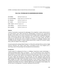
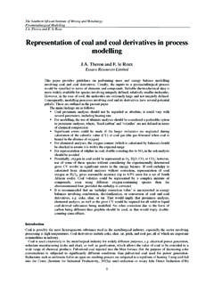
4 655 THE EXTRACTIVE metallurgy OF GOLD Storm water diversion trench Toe starter wall PLAN Daywall Delivery Pool main Fence Road " / Under drainage SECTION Figure ILL Typical layout of a tailings dam. Planning Components of a residue disposal system By way of introduction to this section on planning a surface tailings disposal scheme, it is useful to list the various components of a tailings disposal com-plex and briefly describe their purpose. Consideration of each of the COill-656 DISPOSAL OF RESIDUES ponents during the siting, sizing and investigation of potential impoundment sites is important in view of their influence on cost, area provision and future operation.
5 Containment wall or toewall - a wall, usually of compacted earth, to contain the tailings either as a total confining structure or during the early development of the impoundment. Underdrainage system - a system of filter drains to control seepage within the impoundment. Decant system - a pipe system to facilitate the removal of clarified water and stormwater accumulated on the impoundment. Delivery system -pipework, valves and discharge points to convey the pulp to, around and into the impoundment. Return water system - a system of dams, sumps, pumps and pipelines for holding and conveying excess effluent and stormwater from the tail-ings dam to the plant.
6 Stormwater diversion system - a system of trenches and bunds con-structed around an impoundment to control and divert external storm-water around the impoundment. Stormwater catchment paddocks - a system of paddocks constructed around the toe of the impoundment to capture, control and store storm-water and sediment eroded from the side slopes of the impoundment. Ancillary system -comprising access roads, power supply system, etc. These components are illustrated in Figure , which depicts a plan layout of a typical gold tailings dam. Sizing Depositional area requirements The first step in planning and providing for tailings disposal is the definition of the required area of ground which will meet the constraints of total volumetric capacity required for a manageable height of dam and rate of rise or operating cycle time.
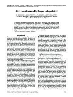
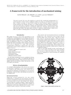
7 At this stage of planning, a maximum height of 35 -40 m would be assumed and a rate of rise selected on the basis of pulp density and anticipated foundation soils. Figure , as proposed by Wates (1983), serves as a guide. Typically, gold tailings have a settled density in a tailings dam of be-tween 1250 and 1650 kg/m3 depending on the depth of tailings. A reasonable figure to assume for sizing calculations is 1450 kg/m3 The re-quired tailings dam area can then be calculated very simply from the equation: Area, m2 = ( X 12) / (1,45 X ROR) ( ) where t. p. m. = dry tons deposited per month, and ROR = allowable rate of rise (m/yr).
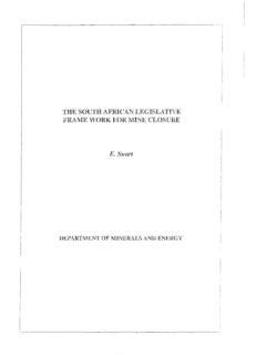
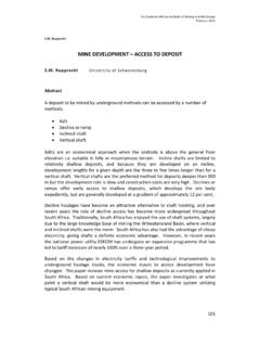
8 This area takes no account of ground topography, or of reduction of area as the dam grows. Figure gives an indication of factors which could be applied to the depositional area of approximately square dams on sites with a significant ground slope. 657 THE EXTRACTIVE metallurgy OF GOLQ Ld. 1,0 I w/s 00 1,1 I 6,0 1,2 1,3 1,4 1,5 1,6 I I I I 3,0 2,0 1,5 1,0 Density of tailings pulp Figure Rate of rise versus tailings pulp density. The actual rate of rise on a sloping site will tend initially to be above the calculated figure and thereafter will decrease to just above this figure when all ground is covered. From this stage the rate of rise will begin to in-crease again due to the reducing area as the side slopes of the dam are formed.
9 In the case of paddock dams, at rates of rise above the limits implied by Figure , cycle times between lifts become too short to allow suffi-cient drying and desiccation of each lift. Access becomes difficult and, while rates of rise in excess of 2,5 mlyr can be tolerated for limited periods of time, above a height of 2,5 to 5 rn, stability problems will eventually result. 658 DISPOSAL OF RESIDUES Area required = Area x multiplying factor I" 1,3 '<6 S ., "0 <l) '""' ., I I J ;:I ~ J > < 0 1,2 '""' 0. 0. ~ '""' ~ <is I / I / bJl f 1,1 S / / L ., <l) '""' V <t: /' ./ ~ 1,0 /' 0,5 1,0 1,5 2,0 3,0 3,5 2,5 Average ground slope (0/0) Figure Correction to dam area for various ground slopes.
10 The anticipated period of usage of the site may be calculated from: Time (years) (hmax X 1,45) x (area) / t. p. m. X 12 ( ) hmax area maximum height, m average area, m2 dry tons deposited per month. At this level of planning, a maximum height of 35 m would be a reasonable assumption. Detailed design and the provision of suitably positioned drainage media could facilitate an increase in this height to 50 m and more, provided rate of rise constraints are not exceeded. If the period of usage of the site from the above calculations proves inadequate it is advisable to reverse the calculation to give the depositional area required to attain a height of 35 m.