Transcription of Chapter 11: Computed Tomography - Human Health Campus
1 IAEAI nternational Atomic Energy AgencySlide set of 190 slides based on the Chapter authored byJ Gelijnsof the IAEA publication (ISBN 978-92-0-131010-1):Diagnostic Radiology Physics: A Handbook for Teachers and StudentsObjective:To familiarize the student with CT scanning principles, acquisition and reconstruction, technology and image 11: Computed TomographySlide set prepared by S. EdyveanIAEACHAPTER OF CT The CT imaging Image reconstruction and Computed Tomography image qualityBibliographyDiagnostic Radiology Physics: a Handbook for Teachers and Students Chapter 11, 2 IAEA Clinical Computed Tomography (CT) was introduced in 1971 - limited to axial imaging of the brain in neuroradiology It developed into a versatile 3D whole body imaging modality for a wide range of applications in for example oncology, vascular radiology, cardiology, traumatology and interventional radiology.
2 Computed Tomography can be used for diagnosis and follow-up studies of patients planning of radiotherapy treatment screening of healthy subpopulations with specific risk factors. INTRODUCTIOND iagnostic Radiology Physics: a Handbook for Teachers and Students Chapter 11, 3 IAEA Nowadays dedicated CT scanners are available for special clinical applications, such as For radiotherapy planning - these CT scanners offer an extra wide bore, allowing the CT scans to be made with a large field of view. The integration of CT scanners in multi modality imaging applications, for example by integration of a CT scanner with a PET scanner or a SPECT INTRODUCTIOND iagnostic Radiology Physics: a Handbook for Teachers and Students Chapter 11, 4 IAEA Other new achievements for dedicated diagnostic imaging new achievements concerns for example the development of a dual source CT scanner (a CT scanner that is equipped with two X-ray tubes), and a volumetric CT scanner (a 320 detector row CT scanner that allows for scanning entire organs within one rotation).
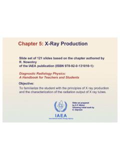
3 INTRODUCTIOND iagnostic Radiology Physics: a Handbook for Teachers and Students Chapter 11, 5 IAEA CT scanning is perfectly suited for 3D imaging and used in, for example, brain, cardiac, musculoskeletal, and whole body CT imaging The images can be presented as impressive colored 3D rendered images, but radiologists usually rely more on black and white, 2D images, being either the 2D axial images, or 2D INTRODUCTIOND iagnostic Radiology Physics: a Handbook for Teachers and Students Chapter 11, 6 IAEA The purpose of a Computed Tomography acquisition is to measure x ray transmission through a patient for a large number of views. CT X-ray projection, attenuation and acquisition of transmission profilesx-ray tubedetector elementattenuated beamattenuated beamDiagnostic Radiology Physics.
4 A Handbook for Teachers and Students Chapter 11, 7 IAEA Different views are achieved in Computed Tomography primarily by using detectors with hundreds of detector elements along the detector arc (generally 800-900 detector elements), by rotation of the x ray tube around the patient, taking about 1000 angular measurements and by tens or even hundreds of detector rows aligned next to each other along the axis of CT X-ray projection, attenuation and acquisition of transmission profiles~ 800 900 detector elements~ 1000 angular measurements1 320 detector rowsDiagnostic Radiology Physics: a Handbook for Teachers and Students Chapter 11, 8 IAEA The values that are assigned to the pixels in a CT image are associated with the average linear attenuation coefficient (m-1) of the tissue represented within that pixel.
5 The linear attenuation coefficient ( ) depends on the composition of the material, the density of the material, and the photon energy as seen in Beer s law: where I(x) is the intensity of the attenuated X ray beam, I0the unattenuated X ray beam, and xthe thickness of the CT X-ray projection, attenuation and acquisition of transmission profiles x0eII(x) =I0I(x)x Diagnostic Radiology Physics: a Handbook for Teachers and Students Chapter 11, 9 IAEA Beer s law only describes the attenuation of the primary beam and does not take into account the intensity of scattered radiation that is generated. For poly-energetic X ray beams Beer s law should strictly be integrated over all photon energies in the X ray spectrum.
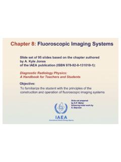
6 In the back projection methodologies developed for CT reconstruction algorithms, this is generally not implemented Instead typically a pragmatic solution is to assume where Beer s law can be applied using one value representing the average photon energy of the X ray spectrum. This assumption causes inaccuracies in the reconstruction and leads to the beam hardening CT X-ray projection, attenuation and acquisition of transmission profilesDiagnostic Radiology Physics: a Handbook for Teachers and Students Chapter 11, 10 IAEA As an X ray beam is transmitted through the patient, different tissues are encountered with different linear attenuation coefficients. The intensity of the attenuated X ray beam, transmitted a distance d, can be expressed CT X-ray projection, attenuation and acquisition of transmission profiles = d0 (x)dx0eII(d)x-ray tubedetector elementattenuationI0I(d)ddx,2dx,3 x2 x3dx,1 Radiology Physics: a Handbook for Teachers and Students Chapter 11, CT X-ray projection, attenuation and acquisition of transmission profilesvoxelpixel array A CT image is composed of a matrix of pixels representing the average linear attenuation co-efficient in the associated volume elements (voxels).
7 Diagnostic Radiology Physics: a Handbook for Teachers and Students Chapter 11, CT X-ray projection, attenuation and acquisition of transmission profiles Illustration: a simplified 4 x 4 matrix representing the measurement of transmission along one line. Each element in the matrix can in principle have a different value of the associated linear attenuation coefficient. The equation for the attenuation can be expressed as: === 4i1ii x 0eII(d)Diagnostic Radiology Physics: a Handbook for Teachers and Students Chapter 11, 13 IAEA From the above it can be seen that the basic data needed for CT is the intensity of the attenuated and unattenuated X ray beam, respectively I(d) and I0, and that this can be measured.
8 Image reconstruction techniques can then be applied to derive the matrix of linear attenuation coefficients, which is the basis of the CT CT X-ray projection, attenuation and acquisition of transmission profilesDiagnostic Radiology Physics: a Handbook for Teachers and Students Chapter 11, 14 IAEA In CT the matrix of reconstructed linear attenuation coefficients ( material) is transformed into a corresponding matrix of Hounsfield units (HUmaterial), where the HU scale is expressed relative to the linear attenuation coefficient of water at room temperature ( water): It can be seen that HUwater= 0 as ( material= water), HUair= -1000 as ( material= 0) HU=1 is associated with of the linear attenuation coefficient of water.
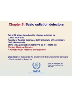
9 CT Hounsfield Units1000 HUwaterwatermaterialmaterial =Diagnostic Radiology Physics: a Handbook for Teachers and Students Chapter 11, 15 IAEA Typical values for body tissues. The actual value of the Hounsfield unit depends on the composition of the tissue or material, the tube voltage, and the CT Hounsfield UnitsSubstanceHounsfield unit (HU)Compact bone+1000 (+300 to +2500)Liver+ 60 (+50 to +70)Blood+ 55 (+50 to +60)Kidneys+ 30 (+20 to +40)Muscle+ 25 (+10 to +40)Brain, grey matter+ 35 (+30 to +40)Brain, white matter+ 25 (+20 to +30)Water0 Fat- 90 (-100 to -80)Lung- 750 (-950 to -600)Air- 1000 Diagnostic Radiology Physics: a Handbook for Teachers and Students Chapter 11, 16 IAEACT number window Hounsfield units are usually visualized in an eight bit grey scale offering only 128 grey values.
10 -1000 HU0 HU4000+ HUWWWLWWWL-1000 HU0 HU4000+ HU The display is defined using Window level (WL) as CT number of mid-grey Window width (WW) as the number of HU from black -> whiteDiagnostic Radiology Physics: a Handbook for Teachers and Students Chapter 11, 17 IAEA The choice of WW and WL is dictated by clinical need Optimal visualization of the tissues of interest in the CT image can only be achieved by selecting the most appropriate window width and window level. Different settings of the WW and WL are used to visualize for example soft tissue, lung tissue or bone. CT Hounsfield UnitsDiagnostic Radiology Physics: a Handbook for Teachers and Students Chapter 11, 18 IAEA Same image data at different WL and WWWL -593, WW 529 WL -12, WW 400-1000 HU4000+ HUWWWL0 HU-1000 HU4000+ CT Hounsfield UnitsDiagnostic Radiology Physics: a Handbook for Teachers and Students Chapter 11, 19 GSTT Nuclear Medicine 06 IAEA The minimum bit depth that should be assigned to the Hounsfield unit is 12, this enables creating a Hounsfield scale that runs from 1024 HU to +3071 HU, thus covering most clinically relevant tissues.