Transcription of Chapter 12 SEISMIC DESIGN REQUIREMENTS FOR BUILDING …
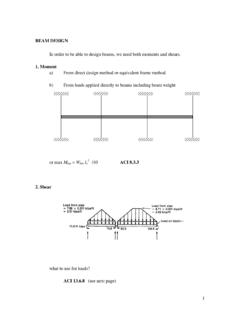
1 P1: 15, 200517:48 Chapter 12 SEISMIC DESIGN REQUIREMENTS FOR BUILDING STRUCTURAL DESIGN Basic SEISMIC analysis and designprocedures to be used in the DESIGN of BUILDING structures and theircomponents shall be as prescribed in this section. The buildingstructure shall include complete lateral and vertical force-resistingsystems capable of providing adequate strength, stiffness, and en-ergy dissipation capacity to withstand the DESIGN ground motionswithin the prescribed limits of deformation and strength DESIGN ground motions shall be assumed to occur along anyhorizontal direction of a BUILDING structure. The adequacy of thestructural systems shall be demonstrated through the constructionof a mathematical model and evaluation of this model for the ef-fects of DESIGN ground motions. The DESIGN SEISMIC forces, andtheir distribution over the height of the BUILDING structure, shall beestablished in accordance with one of the applicable proceduresindicated in Section and the corresponding internal forcesand deformations in the members of the structure shall be deter-mined.
2 An approved alternative procedure shall not be used toestablish the SEISMIC forces and their distribution unless the cor-responding internal forces and deformations in the members aredetermined using a model consistent with the procedure :As an alternative, the simplified DESIGN procedures ofSection is permitted to be used in lieu of the REQUIREMENTS of through , subject to all of the limitations contained in Member DESIGN , Connection DESIGN , and Deforma-tion members, including those not part of theseismic force resisting system, shall be provided with adequatestrength to resist the shears, axial forces, and moments determinedin accordance with this standard, and connections shall developthe strength of the connected members or the forces indicated inSection The deformation of the structure shall not exceedthe prescribed limits where the structure is subjected to the designseismic Continuous Load Path and load path, or paths.
3 With adequate strength and stiffness shallbe provided to transfer all forces from the point of application tothe final point of resistance. All parts of the structure between sep-aration joints shall be interconnected to form a continuous path tothe SEISMIC force resisting system, and the connections shall becapable of transmitting the SEISMIC force (Fp)induced by the partsbeing connected. Any smaller portion of the structure shall be tiedto the remainder of the structure with elements having a designstrength capable of transmitting a SEISMIC force of timesthe short period DESIGN spectral response acceleration parame-ter,SDS,times the weight of the smaller portion or 5 percent ofthe portion s weight, whichever is greater. This connection forcedoes not apply to the overall DESIGN of the SEISMIC force resistingsystem. Connection DESIGN forces need not exceed the maximumforces that the structural system can deliver to the Connection to connection for re-sisting a horizontal force acting parallel to the member shallbe provided for each beam, girder, or truss either directly to itssupporting elements, or to slabs designed to act as the connection is through a diaphragm, then the member ssupporting element must also be connected to the diaphragm.
4 Theconnection shall have a minimum DESIGN strength of 5 percent ofthe dead plus live load Foundation foundation shall be designed toresist the forces developed and accommodate the movements im-parted to the structure by the DESIGN ground motions. The dynamicnature of the forces, the expected ground motion, the DESIGN ba-sis for strength and energy dissipation capacity of the structure,and the dynamic properties of the soil shall be included in thedetermination of the foundation DESIGN criteria. The DESIGN andconstruction of foundations shall comply with Section Material DESIGN and Detailing elements including foundation elements shall conform to thematerial DESIGN and detailing REQUIREMENTS set forth in Chapter STRUCTURAL SYSTEM Selection and basic lateral and verticalseismic force resisting system shall conform to one of the typesindicated in Table or a combination of systems as permittedin Sections , , and Each type is subdivided bythe types of vertical elements used to resist lateral SEISMIC structural system used shall be in accordance with the seismicdesign category and height limitations indicated in Table appropriate response modification coefficient,R,systemoverstrength factor, 0,and the deflection amplification factor,Cd,indicated in Table shall be used in determining thebase shear.
5 Element DESIGN forces, and DESIGN story selected SEISMIC force-resisting system shall be designedand detailed in accordance with the specific REQUIREMENTS for thesystem per the applicable reference document and the additionalrequirements set forth in Chapter force resisting systems that are not contained inTable are permitted if analytical and test data are submittedthat establish the dynamic characteristics and demonstrate the lat-eral force resistance and energy dissipation capacity to be equiva-lent to the structural systems listed in Table for equivalentresponse modification coefficient,R,system overstrength coeffi-cient, 0,and deflection amplification factor,Cd, Combinations of Framing Systems in Different SEISMIC force resisting systems are permitted tobe used to resist SEISMIC forces along each of the two orthog-onal axes of the structure.
6 Where different systems are used,the respectiveR,Cd,and 0coefficients shall apply to eachsystem, including the limitations on system use contained inTable Combinations of Framing Systems in the Same different SEISMIC force resisting systems are usedin combination to resist SEISMIC forces in the same direction ofstructural response, other than those combinations considered asMinimum DESIGN Loads for Buildings and Other Structures119P1: 15, 200517:48 TABLE DESIGN COEFFICIENTS AND FACTORS FOR SEISMIC FORCE RESISTING SYSTEMSS eismic Force Resisting SystemASCE 7 Section whereDetailing Requirementsare SpecifiedResponseModificationCoefficient ,RaSystemOverstrengthFactor, 0gDeflectionAmplificationFactor,CdbStruc tural System Limitationsand BUILDING Height (ft) LimitcSeismic DESIGN CategoryBCDdEdFeA. BEARING WALL SYSTEMS1. Special reinforced concrete shear and Ordinary reinforced concrete and Detailed plain concrete shear and Ordinary plain concrete shear and Intermediate precast shear and Ordinary precast shear and Special reinforced masonry shear and Intermediate reinforced masonry and Ordinary reinforced masonry Detailed plain masonry shear Ordinary plain masonry shear Prestressed masonry shear Light-framed walls sheathed withwood structural panels rated for shearresistance or steel , ,and Light-framed walls with shear panelsof all other , ,and Light-framed wall systems using flatstrap , ,and BUILDING FRAME SYSTEMS1.
7 Steel eccentrically braced frames,moment resisting connections atcolumns away from Steel eccentrically braced frames,non-moment-resisting, connections atcolumns away from Special steel concentrically Ordinary steel concentrically Special reinforced concrete shear and Ordinary reinforced concrete and Detailed plain concrete shear and Ordinary plain concrete shear and Intermediate precast shear and Ordinary precast shear and Composite steel and concreteeccentrically braced Composite steel and concreteconcentrically braced Ordinary composite steel and concretebraced Composite steel plate shear Special composite reinforced concreteshear walls with steel Ordinary composite reinforcedconcrete shear walls with Special reinforced masonry shear Intermediate reinforced masonry Ordinary reinforced masonry Detailed plain masonry shear Ordinary plain masonry shear 7-05P1: 15, 200517.
8 48 TABLE DESIGN COEFFICIENTS AND FACTORS FOR SEISMIC FORCE RESISTING SYSTEMS (continued) SEISMIC Force Resisting SystemASCE 7 Section whereDetailing Requirementsare SpecifiedResponseModificationCoefficient ,RaSystemOverstrengthFactor, 0gDeflectionAmplificationFactor,CdbStruc tural System Limitationsand BUILDING Height (ft) LimitcSeismic DESIGN CategoryBCDdEdFe22. Prestressed masonry shear Light-framed walls sheathed withwood structural panels rated for shearresistance or steel , ,and Light-framed walls with shear panelsof all other , ,and Buckling-restrained braced frames,non-moment-resisting Buckling-restrained braced frames,moment-resisting Special steel plate shear MOMENT-RESISTING FRAMESYSTEMS1. Special steel moment and Special steel truss moment Intermediate steel moment , , , ,and ,iNPhNPi4. Ordinary steel moment.
9 And Special reinforced concrete and Intermediate reinforced concretemoment Ordinary reinforced concrete Special composite steel and concretemoment and Intermediate composite Composite partially restrained Ordinary composite moment SYSTEMS WITH SPECIALMOMENT FRAMES CAPABLE OFRESISTING AT LEAST 25% OFPRESCRIBED SEISMIC Steel eccentrically braced Special steel concentrically Special reinforced concrete shear Ordinary reinforced concrete Composite steel and concreteeccentrically braced Composite steel and concreteconcentrically braced Composite steel plate shear Special composite reinforced concreteshear walls with steel Ordinary composite reinforcedconcrete shear walls with Special reinforced masonry shear Intermediate reinforced masonry Buckling-restrained braced Special steel plate shear DESIGN Loads for Buildings and Other Structures121P1: 15, 200517:48 TABLE DESIGN COEFFICIENTS AND FACTORS FOR SEISMIC FORCE RESISTING SYSTEMS (continued) SEISMIC Force-Resisting SystemASCE 7 Section whereDetailing Requirementsare SpecifiedResponseModificationCoefficient ,RaSystemOverstrengthFactor, 0gDeflectionAmplificationFactor,CdbStruc tural System Limitationsand BUILDING Height (ft) LimitcSeismic DESIGN CategoryBCDdEdFeE.
10 DUAL SYSTEMS WITHINTERMEDIATE MOMENT FRAMESCAPABLE OF RESISTING AT LEAST25% OF PRESCRIBED Special steel concentrically ,k2. Special reinforced concrete shear Ordinary reinforced masonry Intermediate reinforced masonry Composite steel and concreteconcentrically braced Ordinary composite braced Ordinary composite reinforcedconcrete shear walls with Ordinary reinforced concrete WALL-FRAMEINTERACTIVE SYSTEM WITHORDINARY REINFORCEDCONCRETE MOMENT FRAMES ANDORDINARY REINFORCEDCONCRETE SHEAR and CANTILEVERED COLUMNSYSTEMS DETAILED TO CONFORMTOTHE REQUIREMENTS Special steel moment and Intermediate steel moment ,iNPh,i3. Ordinary steel moment ,iNPh,i4. Special reinforced concrete and Intermediate concrete moment Ordinary concrete moment Timber STEEL SYSTEMS NOTSPECIFICALLY DETAILED FORSEISMIC RESISTANCE, EXCLUDINGCANTILEVER COLUMN modification coefficient,R,for use throughout the standard.