Transcription of Chapter 12 –Stormwater Sand Filters
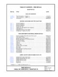
1 VDOT BMP Design Manual of Practice i Chapter 12 stormwater sand Filters Chapter 12 stormwater sand Filters TABLE OF CONTENTS Overview of Practice .. 1 Site Constraints and Siting of the filter .. 5 Minimum Drainage Area .. 5 Maximum Drainage Area .. 5 Elevation of Site Infrastructure .. 5 Depth to Water Table and/or Bedrock .. 5 Existing Utilities .. 6 Wetlands .. 6 Upstream Sediment Loading .. 6 Aesthetic Considerations .. 6 Control of Surface Debris .. 6 Hydrocarbon Loading .. 7 Perennial and Chlorinated Flows .. 7 Surface Loading .. 7 General Design Guidelines .. 8 Isolation of the Water Quality Volume (WQV) .. 8 sand filter Media .. 9 Discharge Flows .. 9 filter Sizing .. 9 Design Process .. 10 Step 1. Compute the Required Water Quality Volume .. 10 Step 2A. Size filter and Pre-Treatment Sedimentation Chamber Washington underground Vault sand filter .
2 11 Step 2B. Size filter and Pre-Treatment Sedimentation Chamber Delaware sand filter .. 15 Step 2C. Size filter and Pre-Treatment Sedimentation Chamber Austin Surface sand filter .. 17 Step 3. Establish the Crest Elevation of the Water Quality Diversion Weir .. 21 Table of Contents VDOT BMP Design Manual of Practice ii Chapter 12 stormwater sand Filters LIST OF TABLES Table Appropriate Drainage Area by filter Type .. 5 Table Hydrologic Characteristics of Example Project Site .. 10 Table filter Surface Dimensions .. 13 Table Design Summary sand filter .. 14 Table Delaware filter Surface Dimensions .. 17 Table Austin filter Surface Dimensions .. 18 Table Particle Settling Velocities (MDE, 2000) .. 19 Table Design Summary Austin sand filter .. 20 LIST OF FIGURES Figure Washington underground Vault sand filter .
3 2 Figure Delaware sand filter .. 3 Figure Austin Surface sand filter .. 4 Figure Flow-splitting Diversion Weir (Bell, Warren, 1993) .. 8 Figure Flow-Splitting Manhole Structure .. 9 Figure sand filter Cross Section .. 11 Figure Delaware sand filter Cross Section .. - Overview of Practice VDOT BMP Design Manual of Practice 1 of 21 Chapter 12 stormwater sand Filters Overview of Practice stormwater sand Filters are practices employed when the runoff from a site is expected to contain very high pollutant levels. These sand Filters function by first pre-treating and temporarily storing runoff to remove the bulk of the large particle sediment, then percolating the runoff through the filter s sand media. As runoff Filters through the sand media, water quality is improved through physical, chemical, and biological mechanisms. Various types of stormwater sand Filters exist, and their application can be tailored to meet individual site needs.
4 The most common types of stormwater sand Filters are the Washington underground vault sand filter , the Delaware sand filter , and the Austin surface sand filter . stormwater sand Filters act primarily as water quality BMPs; however, the water quality volume entering the filter is detained and released at a rate potentially capable of providing downstream channel erosion control. Peak rate control of the 10-year and greater storm events is typically beyond the capacity of a stormwater filtering system, and may require the use of a separate structural peak rate reduction facility. stormwater sand Filters are commonly used in urbanized settings where entering runoff is generated from areas whose imperviousness ranges from 67 100 percent. The primary cause of failure in stormwater filtering systems is the clogging of the sand media through excessive sediment loading.
5 The Filters described in this document should not be used on sites having an impervious cover of less than 65 percent. The Virginia stormwater Management Handbook, (DCR, 1999, Et seq., Et seq.) identifies three types of stormwater stand Filters appropriate for use in the state. These are the Washington underground Vault sand filter , the Delaware sand filter , and the Austin Surface sand filter . Each filter type is described briefly in the following section. - Overview of Practice VDOT BMP Design Manual of Practice 2 of 21 Chapter 12 stormwater sand Filters Figure Washington underground Vault sand filter (Virginia stormwater Management Handbook, 1999, Et seq.) The Washington underground vault sand filter shown in Figure can be either precast or cast in place and is composed of three chambers. The first chamber is a three foot deep plunge pool which absorbs energy and pre-treats runoff by trapping sediment and floating organic matter.
6 The first chamber is hydraulically connected to the second chamber containing the sand filter media. Finally, the third chamber serves as a collection point for filtered runoff, where it is then directed to the downstream storm sewer. This type of filter is typically constructed offline, with only the site water quality volume directed to the structure. - Overview of Practice VDOT BMP Design Manual of Practice 3 of 21 Chapter 12 stormwater sand Filters Figure Delaware sand filter (Virginia stormwater Management Handbook, 1999, Et seq.) The Delaware sand filter shown in Figure was originally conceived as an online facility (unlike the Washington sand filter ), processing all runoff leaving its contributing drainage shed up to the point that overflow is reached. When applied on VDOT projects, the Delaware sand filter should be equipped with a flow-splitting device such that only the site water quality volume is treated by the filter .
7 The Delaware sand filter is characterized by two parallel chambers, one serving as pre-treatment sedimentation chamber and the other holding the sand filter media. The pre-treatment chamber holds a permanent pool analogous to that of a septic tank. Flow entering the pre-treatment chamber causes the water level in the chamber to rise and eventually spill into the filter chamber where full treatment occurs. Upon filtering through the sand media, treated runoff is collected in the clearwell located at the lower end of the structure. From there, the treated runoff is directed to the receiving storm sewer. - Overview of Practice VDOT BMP Design Manual of Practice 4 of 21 Chapter 12 stormwater sand Filters Figure Austin Surface sand filter (Virginia stormwater Management Handbook, 1999, Et seq.) The Austin surface sand filter , as shown in Figure , is composed of an open basin characterized by a pre-treatment sedimentation basin that is often large enough to hold the entire water quality volume from the contributing drainage shed.
8 This volume is then released into the sand bed filtration chamber over a period of 24 hours. Alternative designs employ a much smaller sedimentation chamber, and compensate for the increased clogging potential by increasing the surface area of the filtration chamber. Typically, both chambers of the Austin filter are constructed of concrete; however, when soil conditions and/or the application of a geomembrane liner permit, the pre-treatment sedimentation chamber may be constructed into the ground. - Site Constraints and Siting of the filter VDOT BMP Design Manual of Practice 5of 21 Chapter 12 stormwater sand Filters Site Constraints and Siting of the filter The designer must consider a number of site constraints in addition to the contributing drainage area s impervious cover when a stormwater sand filter is proposed.
9 These constraints are discussed as follows. Minimum Drainage Area The minimum drainage area contributing to an intermittent stormwater sand filter is not restricted. These types of Filters are best suited to small drainage areas. Maximum Drainage Area The maximum drainage area to a single stormwater sand filter varies by filter type. Table shows the impervious acreage which may be directed to a single filter , as a function of filter type. filter Type Appropriate Drainage Shed (Impervious Acres) underground Vault Delaware Maximum Austin Surface Greater than Table Appropriate Drainage Area by filter Type Austin surface sand Filters have been applied on sites with drainage areas as large as 30 acres; however on sites greater than 10 acres, despite a reduction in cost per volume of runoff treated arising from the economy of scale, the cost-effectiveness of an Austin sand filter is often poor when compared to alternative BMP options.
10 Elevation of Site Infrastructure Whenever possible, stormwater filtering systems should be designed to operate exclusively by gravity flow. This requires close examination of the difference in elevation between the filter s discharge point (manhole, pipe, or receiving channel) and the storm sewer discharging runoff into the filter . This difference in elevation dictates the hydraulic head available on the filter while still remaining in a state of gravity flow. When the filter s clearwell discharge point is below the elevation of the downstream receiving point, an effluent pump is a viable alternative; however, this option requires routine scheduled maintenance by trained crews knowledgeable in the maintenance of such mechanical equipment. Depth to Water Table and/or Bedrock The liner or concrete shell of a sand filter should generally be located 2 to 4 feet above the site seasonally high water table.
