Transcription of Chapter 13 BUILDING A HOMEBREW HF RECEIVER
1 1. Chapter 13, Harris CRYSTAL SETS TO SIDEBAND Frank W. Harris 2010, REV 12 Chapter 13 BUILDING A HOMEBREW HF RECEIVER The Vanishing Art The 1986 ARRL Amateur Radio Handbook reported that hardly anyone was BUILDING HOMEBREW ham receivers. Since then, handbooks have had fewer and fewer practical details on BUILDING radios. Out of hundreds of contacts, so far I ve only worked three guys, George, K7DU, Mike, N MF, and Biz, WD HCO, who were using HOMEBREW receivers for the QSO. Two of these receivers were made from vacuum tubes.
2 The third HOMEBREW RECEIVER that I worked was an old-fashioned super-regenerative design. However, the super-regenerative was implemented with modern FET transistors and integrated circuits. All three of these receivers seemed to have no trouble hearing me on 40 meter CW. I talked to one other fellow, Gil, N1 FED who told me he had just finished a vacuum tube RECEIVER . Unfortunately, it was performing so poorly he was still using his modern transceiver on the air. Gil told me he didn t like transistors. I guess he found printed circuit boards and those pesky oscillations too much trouble.
3 In spite of this pessimism, you CAN build transistorized receivers that work reasonably well. I built mine because I was intrigued by mysterious circuits like balanced mixers, product detectors, cascode amplifiers, and crystal ladder filters. Before this project, I could recite the purposes of these circuits, but I had no feel for how they worked and why receivers are designed the way they are. What better way to learn than to build one? What s a reasonable goal? An adequate performance communications RECEIVER 2.
4 Chapter 13, Harris My RECEIVER is based on the High Performance Communications RECEIVER designed by W7 ZOI and K5 IRK described in most of the annual ARRL Handbooks in the 1980s . In my opinion High Performance is optimistic, but certainly adequate performance is realistic. I define adequate sensitivity and noise figure to mean that I can hear the DX and QRPs that other stations are working. Before I built the RECEIVER described here, I often had the impression I was hearing only the loudest signals.
5 For me, adequate selectivity means that it's good enough for CW QSOs in the evening on 20 and 40 Meters. On these bands there are often dozens of narrow CW signals operating within a few hundred Hertz of each other. With a 10 KHz bandpass you may hear many stations simultaneously and not be able to copy any of them. Adequate sensitivity will allow you to hear most QRP signals. I believe that 45 years ago hardly anyone had receivers that were adequate for QRP contacts. When I was a novice, my first transmitter was a 7-watt HOMEBREW for 40 and 80 meters.
6 It was a close copy of a design in the 1957 Handbook. I know it worked OK, because I talked to my novice buddies around town. Unfortunately I hardly worked anyone outside of town. It wasn t until I bought a 50-watt commercial kit, just like all the other novices, that I was able to talk to all the same stations my friends were working. I was still using the same dipole antenna, so I can only assume the improvement was the extra power. The sensitivity of the RECEIVER described in this Chapter is well under microvolt on 80 meters and lower bands that have no RF preamplifiers.
7 On the upper bands where the RECEIVER has preamplifiers I could hear a calibrated signal source at microvolts. Wow! No wonder I can hear those QRPs. In the old days sensitivity less than 1 microvolt was considered hot stuff. Another issue is adequate stability. When your RECEIVER is equipped with sharp crystal filters, it is vital that the VFO and crystal oscillators are stable enough that the signals you're listening to do not drift in and out of your passband. If you build a VFO like the one described in Chapter 10, you will have no drift troubles.
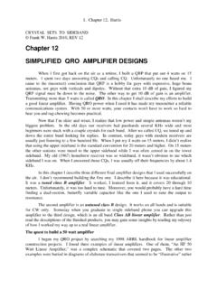
8 Does it have to be so complicated? Looking at the block diagram above, each one of those blocks represents one to three transistor stages. The front-end converter has three transistor stages for each separate HF band. That means you need to build about 20 transistor amplifier or oscillator stages for the converters to cover all the bands. You re probably wondering if there isn t some simple RECEIVER you can build that will get you on the air rapidly. The best news is that you can build the above RECEIVER in stages.
9 The core of the all-band HF RECEIVER is a quality 80 meter RECEIVER . You can build that first, then at least you ll be in business on 80 meters. In the beginning you can also do without the loudspeaker and multiple crystal filters. After you have a functioning RECEIVER , you can add features and the converters to hear the other hambands. Yes, you can build a less complicated RECEIVER , but I doubt it will be adequate. My direct conversion RECEIVER in Chapter 7 worked well, but was not selective enough. There are modern super-regenerative RECEIVER designs with two or three integrated circuits that MAY be pretty good, but I haven t built one, so I m not convinced.
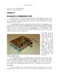
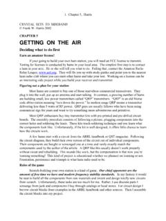
10 Chapter 14 describes a vacuum tube regenerative RECEIVER that was great fun to build and quite good for listening to foreign short wave broadcast stations. Unfortunately, it was NOT selective and sensitive enough for ham communications. In summary, YES, a decent ham RECEIVER does have to be complicated. 3. Chapter 13, Harris A homemade ham RECEIVER built in 1967 A homebuilt ham RECEIVER from 40 years ago is shown above. It has 11 tubes, a simple crystal filter, and covers 80 through 10 meters.