Transcription of Chapter 14-DESIGN CONSIDERATIONS FOR WELDING
1 DESIGN CONSIDERATIONS FOR WELDING Apart from resistance spot WELDING (RSW), three processes are most commonly used for WELDING metal stampings and fabrications: gas metal arc WELDING (GMAW) or MIG; gas tungsten arc WELDING (GTAW) or TIG; and gas WELDING . Although a high initial investment is necessary, laser WELDING is being more widely employed by companies requiring large quantities of multi-point welds. This method employs robots, WELDING at speeds of up to 150 inches ( m) per minute. Other processes--plasma arc, ultrasonic, and electron beam WELDING --are also available, but these methods are usually restricted to WELDING of particular materials with special design requirements, such as microelectronic and aerospace components.
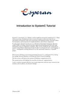
2 Suitability for general sheet metal applications is limited, and processing may be cost-prohibitive. Gas metal arc WELDING , commonly called MIG (metal inert gas), creates an arc between a continuous wire filler metal (consumable electrode) and the sheet metal workpieces. Shielding gas protects both the molten metal and the arc from the atmosphere (Figure 1). This process is suitable for most metals and alloys. Among the most readily weldable materials are: carbon steels, low-alloy steels, stainless steel; 3000, 5000, and 6000-series aluminum alloys; and magnesium alloys.
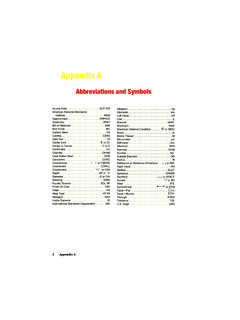
3 Other alloys that can also be MIG-welded via special methods include 2000 and 7000-series aluminum alloys; high-zinc-content copper alloys, and high-strength steels. Gas tungsten arc WELDING , commonly called TIG (tungsten inert gas), produces an arc between a nonconsumable tungsten electrode and the sheet metal workpieces. Inert gas is used to shield the arc and the work; filler metal is optional (Figure 2). Like MIG, TIG can be used to join most metals and alloys, but produces higher quality welds because of the absence of weld spatter. Unlike MIG, TIG can be used to produce fuse-welded joints without filler metal, resulting in minimal eruption above the base metal.
4 Welds can be made in all positions, but the process is considerably slower than other WELDING processes. Compared to MIG, TIG typically takes a minimum of twice as long to complete the same type of weld. Pulsed current is a TIG variation, which can reduce distortion in sheet metal and more easily accommodate a less-than-optimum fit of parts to be welded. Figure 1. Schematic of basic MIG WELDING process and 2. Schematic of TIG WELDING . Oxyfuel gas WELDING (OFW) makes use of the heat generated by an oxygen and acetylene gas (or other gas) flame to weld two components together.
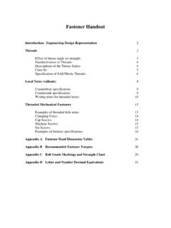
5 Filler metal is supplied by a WELDING rod. This method is declining in use because of heat distortion, and because faster more economical methods are available. Weld Joint Design Figure 3. Common weld joints for stampings and sheet metal fabrications. Several types of joints can be appropriate for welded sheet metal design, among them: butt, corner, edge, lap and T-joints. See Figure 3 for joints typically used for stampings and sheet metal fabrications. In theory, types of joints do differ from types of welds. In practice, however the two terms are often confused.
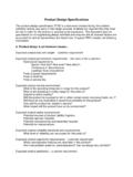
6 For clarification, see Figure 4. The three basic types of welds are fillet, square and grooved. Figure 4. Terminology for joints and welds. Figure 5A. Dimensional recommendations for square-groove butt joint in thin steel sheet. Figure 5B. Butt joint made on short-flanged edges requires no filler metal and helps control melt-through and 5C. Lap joint with a double fillet weld should have a 1 in. (25 mm) minimum overlap. A single fillet and shorter overlap may suffice when less strength is 5D. Compared to a single fillet, a T-joint with a double-fillet weld produces maximum joint strength.
7 Shortest side of the fillet should be equal to the material 5E. Corner-edge joints in thin sheet with a V-groove weld are completed with one pass. For higher strength, a second pass (inside) or backing may be required. A simple jig may be required to minimize distortion and maintain squareness of a corner joint. For joints made on thin sheet certain dimensional recommendations or limitations apply to single-pass fillet and groove welds. See Figures 5A-5E for details. Figure 6. Various corner joints suitable for WELDING of sheet types of joints--butt, corner, edge, lap and "T"--are appropriate for MIG and TIG WELDING .
8 Corner joints, in particular, find extensive use in sheet metal cabinets and enclosures (Figure 6.) Specifying Welds To avoid extra cost and excessive part distortion, the knowledgeable designer avoids over-specifying welds. In structural or dynamically loaded parts where strength and performance are important, the WELDING method is usually specified. In statically loaded parts like cabinets, the method is not as critical, because service loads are relatively small. With a tack weld, for instance, length of weld, size, spacing, location and frequency (number of welds) are typically specified, but not the method.
9 When welds are specified on an engineering drawing, they are often done "by the book," following ANSI/AWS (Figure 7). Although technically correct, following this method may generate many extra hours in part design. Usually it is sufficient to designate welds with notes on the drawing without separately calling out fillet welds, groove welds, etc. This is particularly applicable to WELDING sheet metal parts when the same process is used to make all welds. Some metalforming suppliers suggest that designers not specify the exact method and type of WELDING .
10 This provides increased flexibility, depending on the equipment available, and often results in the most economical choice for the customer. For covers and decorative items, it usually suffices to specify "corners must be filled or smooth," or alternately, to reference a paint or other finishing specification, which simply may designate "no openings." Similarly, chassis design merely requires specifying weld location, leaving the WELDING method up to the supplier. For WELDING corners on a frame or similar component, MIG WELDING is structurally sound and the surface can be readily ground to produce an acceptable surface for painting or other finishing.