Transcription of CHAPTER 16 - GANTRIES - nra.co.za
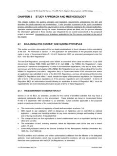
1 GANTRIES 16-1 CHAPTER 16 - GANTRIES DS Temple SCOPE This section covers the inspection of Sign GANTRIES as specified in the applicable CHAPTER of the Specifications. It also covers the special attention which must be given by the engineer s monitoring staff to the specific requirements of setting out, excavations foundations, backfill and, manufacture and erection of the structural steel GANTRIES . FOUNDATIONS Setting Out (Refer to CHAPTER 4) The setting out of the GANTRIES should be carried out in accordance with CHAPTER 3 of this document. However the following points should be noted. Location The gantry location ( km distance) on the structural drawings must tie in with the location given on the road works drawings. Horizontal Clearances Horizontal clearances must be checked prior to the casting of the gantry foundation plinths.
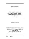
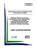
2 Vertical Clearances The vertical clearances as specified on the design drawings should be checked by the Monitoring Staff on site. Photo : Gantry foundation Excavations (Refer to CHAPTER 4) Note that it is preferred that the foundation concrete is cast directly against the sides of the excavation. GANTRIES 16-2 formwork & Falsework (Refer to CHAPTER 6) Steel Reinforcement (Refer to CHAPTER 7) concrete (Refer to CHAPTER 8). Note that durability concrete should be used only in extreme situations. Built-in Items The Monitoring Staff should confirm the orientation of the Holding Down Bolt Groups. Confirm the position of ducts, gantry number and any other built-in items indicated on the drawings. Photo : Completed gantry foundation STRUCTURAL STEEL GANTRIES Materials The Engineer s Monitoring Staff should ensure that the contractor submits a certificate of compliance for: Structural steel for manufacture of gantry Holding down bolts Corrosion Protection The corrosion system as specified on the drawings must be confirmed with the Contractor.
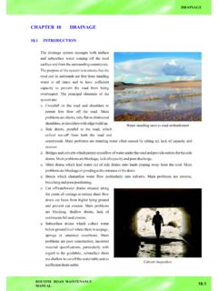
3 The Monitoring Staff should ensure that the manufacturer s Quality Assurance records are made available with the delivery of the GANTRIES . Hot dip galvanizing could be specified as a corrosion protection measure but should be used with caution as this process is still in the experimental stages. Buckling of thin plates occurs during the dipping process due to stress relief in the plates and therefore extreme care should be taken before using this method of corrosion protection. GANTRIES 16-3 Shop Drawings The Monitoring Staff should ensure that shop drawings of the gantry and holding down bolts are submitted for review timeously. Factory Inspection It is a requirement that monitoring staff inspect the structural steel during the manufacturing process. The following important aspects should be checked and verified against the design drawings: Dimensions and thicknesses of the steel plates.
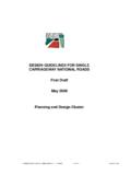
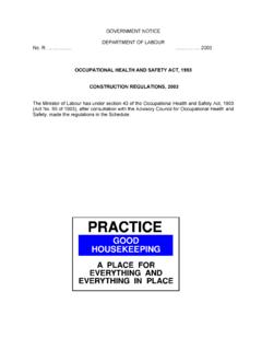
4 Number and spacing of the beam and column stiffener plates. Type, size and quality of all the welds as specified on the drawings. Diameter and length of anchor bolts, as well as the dimensions of the anchor bolt cage. The Monitoring Staff should ensure that the correct grade steel for the anchor bolts and structural steel gantry structure is used. All certificates pertaining to the grade and quality of the steel should be obtained from the manufacturer for construction record purposes. Photo : Gantry manufacturing Erection The Monitoring Staff should ensure that the Contractor submits for review a complete method statement for the erection of the GANTRIES . Accommodation of traffic measures should be submitted in accordance with Road Traffic Signs Manual, CHAPTER 13. Monitoring Staff should ensure that the gantry is erected within the specified tolerances.
5 CHECKING AND TESTING The Monitoring Staff should visit the manufacturing facility during manufacture to ensure that the GANTRIES are being manufactured according to the Manufacturer s Quality Plan. GANTRIES 16-4 Corrosion Protection Reference should be made to the notes on the Detailed Design drawings for the corrosion system to be used. Surface preparation to SA should be checked prior to the application of any corrosion protection. Ensure that the contractor s proposed system for the painted, galvanized or sprayed metal coating conforms to specified requirements. Random testing of the thickness of the various coats of the corrosion protection system should be carried out in the paintshop as well as on the delivered elements and especially on the site painted areas (welded site connections on gantry beams).
6 Records of the tests carried out on the dry film thicknesses (DFT) should be kept. Welding The Monitoring Staff should ensure that the process control adopted by the manufacturer complies with the Project Specification. This can be achieved by including notes on the shop drawings for welding procedures. All QA records of process control of the welds should be provided to the Engineer. Proof of the welder s qualifications should be provided. Ultrasonic testing should be carried out on the following welded connections: Column & base plate connection Column & beam haunch connection At least 10% of the seam welds in the columns* At least 10% of the seam welds in the beams* Gusset plate connections* Site welds** *Where ultrasonic testing is not possible magnetic particle testing should be carried out on at least 50% of the seam welds.
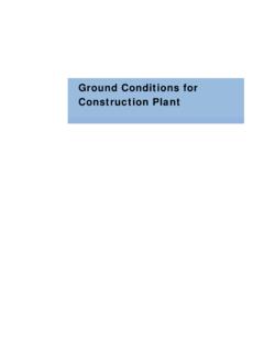
7 **At the very least site welds should be inspected and approved by an independent qualified person. Where possible ultrasonic testing (preferable) or magnetic particle testing should be carried out. It should be noted that these must be done before painting and after the steel has cooled. GANTRIES 16-5 Photo : Gantry erection GANTRY STRUCTURES - CONSTRUCTION MONITORING CHECK LIST The Monitoring Staff should use the Gantry Structures - Construction Monitoring Check List as far as possible to ensure the quality of the gantry structures. GANTRIES 16-6 INDEX TO APPENDICES 16A - GANTRY STRUCTURES GANTRIES 16-7 CONSTRUCTION MONITORING CHECKLIST PROJECT NO. / NAME: .. INSPECTOR S NAME(S): .. STRUCTURE: .. ELEMENT: .. ACTIVITY AND DETAILS APPROVAL SIGNED DATE Y/N N/A Comment 1. EARTHWORKS Setting out Km distance Depth of excavation relative to edge of road Distance from edge of road to foundation centre Can foundation be cast directly against side of excavation as is preferred If not has work space been agreed with Engineer Bearing pressure DCP Tests done Is soil improvement required If so describe Soil improvements tested Provide estimated foundation bearing capacity in kPa Blinding layer Depth to blinding layer relative to edge of road Plan area of blinding layer 2.
8 REINFORCEMENT Footing Bars parallel to road Are they Top 1 and Bottom 1 Bar spacings - 125mm Bar type bottom Bar type top Alternative bar reversed (top bars) Footing Bars perpendicular to road Bar spacings - 250mm Bar type bottom Bar type top Alternative bar reversed (top bars) Plinth Are there the correct number of "U" bars Orientation Location Bar projection height Secondary bars, clips & stirrups Checklist continues on next GANTRY STRUCTURES CHECK LIST(1/4) APPENDIX 16A GANTRIES 16-8 ACTIVITY AND DETAILS APPROVAL SIGNED DATE Y/N N/A Comment 3. ANCHOR BOLTS In workshop Diameter Steel Grade of bolt Bolt cage dimensions On Site On site orientation Location within plinth Projection of bolts Top portion of bolt corrosion protected 4.
9 formwork Footing plan dimensions Is footing formwork required and approved Footing thickness Plinth plan dimensions (parallel and perpendicular to road) Height of plinth Level difference between top of plinth & road edge Cover to rebar - footing 50mm bottom, 75mm sides Cover to rebar - plinth 50mm sides and top Plinth shutter - adequately propped Plinth off shutter surface finish OK 5. SPECIAL CAST IN ITEMS PVC ducts provided if detailed on the drawings Location in plinth (plan) Projection above plinth concrete Checklist continues on next GANTRY STRUCTURES CHECK LIST(2/4) APPENDIX 16A GANTRIES 16-9 ACTIVITY AND DETAILS APPROVAL SIGNED DATE Y/N N/A Comment 6. concrete Pre concrete inspections concrete as per specification & mix design (obtain copy of delivery note) concrete Class W30 MPa Plinth concrete : 50mm < slump < 70mm Proposed curing method Proposed curing period Post concrete inspections Cracks Spalling Honeycomb Shutter kick Repair method 7.
10 STRUCTURAL STEEL Prior to dispatch to site Steel grade certificate and markings Column height plust the beam section Beam length (less the beam section attached to column/s) Column cross section dimensions Beam cross section dimensions Plate thicknesses columns Plate thicknesses beams Special attachment size & plates Stiffener plates, thickness, spacing, fitment Welds visually acceptable and according to drawing Chamfering and preparation for welding Holes setting out Ultrasonic testing of welds - certified On site Method of erection approved Traffic accommodation approved Site welding method approved Site welding quality approved Anchor bolt tightening torque (provide Nm) Grout under base plate - type approved Grout under base plate - installed correctly Checklist continues on next GANTRY STRUCTURES CHECK LIST(3/4) APPENDIX 16A GANTRIES 16-10 ACTIVITY AND DETAILS APPROVAL SIGNED DATE Y/N N/A Comment 8.