Transcription of Chapter 16 HEAT EXCHANGERS - Simon Fraser University
1 PROPRIETARY MATERIAL. 2008 The McGraw-Hill Companies, Inc. Limited distribution permitted only to teachers and educators for course preparation. If you are a student using this manual , you are using it without permission. 16-1 Solutions manual for Introduction to Thermodynamics and Heat Transfer Yunus A. Cengel 2nd Edition, 2008 Chapter 16 HEAT EXCHANGERS PROPRIETARY AND CONFIDENTIAL This manual is the proprietary property of The McGraw-Hill Companies, Inc. ( McGraw-Hill ) and protected by copyright and other state and federal laws. By opening and using this manual the user agrees to the following restrictions, and if the recipient does not agree to these restrictions, the manual should be promptly returned unopened to McGraw-Hill: This manual is being provided only to authorized professors and instructors for use in preparing for the classes using the affiliated textbook.
2 No other use or distribution of this manual is permitted. This manual may not be sold and may not be distributed to or used by any student or other third party. No part of this manual may be reproduced, displayed or distributed in any form or by any means, electronic or otherwise, without the prior written permission of McGraw-Hill. PROPRIETARY MATERIAL. 2008 The McGraw-Hill Companies, Inc. Limited distribution permitted only to teachers and educators for course preparation. If you are a student using this manual , you are using it without permission. 16-2 Types of Heat EXCHANGERS 16-1C Heat EXCHANGERS are classified according to the flow type as parallel flow, counter flow, and cross-flow arrangement. In parallel flow, both the hot and cold fluids enter the heat exchanger at the same end and move in the same direction. In counter-flow, the hot and cold fluids enter the heat exchanger at opposite ends and flow in opposite direction.
3 In cross-flow, the hot and cold fluid streams move perpendicular to each other. 16-2C In terms of construction type, heat EXCHANGERS are classified as compact, shell and tube and regenerative heat EXCHANGERS . Compact heat EXCHANGERS are specifically designed to obtain large heat transfer surface areas per unit volume. The large surface area in compact heat EXCHANGERS is obtained by attaching closely spaced thin plate or corrugated fins to the walls separating the two fluids. Shell and tube heat EXCHANGERS contain a large number of tubes packed in a shell with their axes parallel to that of the shell. Regenerative heat EXCHANGERS involve the alternate passage of the hot and cold fluid streams through the same flow area. In compact heat EXCHANGERS , the two fluids usually move perpendicular to each other. 16-3C A heat exchanger is classified as being compact if > 700 m2/m3 or (200 ft2/ft3) where is the ratio of the heat transfer surface area to its volume which is called the area density.
4 The area density for double-pipe heat exchanger can not be in the order of 700. Therefore, it can not be classified as a compact heat exchanger. 16-4C In counter-flow heat EXCHANGERS , the hot and the cold fluids move parallel to each other but both enter the heat exchanger at opposite ends and flow in opposite direction. In cross-flow heat EXCHANGERS , the two fluids usually move perpendicular to each other. The cross-flow is said to be unmixed when the plate fins force the fluid to flow through a particular interfin spacing and prevent it from moving in the transverse direction. When the fluid is free to move in the transverse direction, the cross-flow is said to be mixed. 16-5C In the shell and tube EXCHANGERS , baffles are commonly placed in the shell to force the shell side fluid to flow across the shell to enhance heat transfer and to maintain uniform spacing between the tubes. Baffles disrupt the flow of fluid, and an increased pumping power will be needed to maintain flow.
5 On the other hand, baffles eliminate dead spots and increase heat transfer rate. 16-6C Using six-tube passes in a shell and tube heat exchanger increases the heat transfer surface area, and the rate of heat transfer increases. But it also increases the manufacturing costs. 16-7C Using so many tubes increases the heat transfer surface area which in turn increases the rate of heat transfer. 16-8C Regenerative heat exchanger involves the alternate passage of the hot and cold fluid streams through the same flow area. The static type regenerative heat exchanger is basically a porous mass which has a large heat storage capacity, such as a ceramic wire mash. Hot and cold fluids flow through this porous mass alternately. Heat is transferred from the hot fluid to the matrix of the regenerator during the flow of the hot fluid and from the matrix to the cold fluid. Thus the matrix serves as a temporary heat storage medium. The dynamic type regenerator involves a rotating drum and continuous flow of the hot and cold fluid through different portions of the drum so that any portion of the drum passes periodically through the hot stream, storing heat and then through the cold stream, rejecting this stored heat.
6 Again the drum serves as the medium to transport the heat from the hot to the cold fluid stream. PROPRIETARY MATERIAL. 2008 The McGraw-Hill Companies, Inc. Limited distribution permitted only to teachers and educators for course preparation. If you are a student using this manual , you are using it without permission. 16-3 The Overall Heat Transfer Coefficient 16-9C Heat is first transferred from the hot fluid to the wall by convection, through the wall by conduction and from the wall to the cold fluid again by convection. 16-10C When the wall thickness of the tube is small and the thermal conductivity of the tube material is high, which is usually the case, the thermal resistance of the tube is negligible. 16-11C The heat transfer surface areas are LDALDAoi21 and ==. When the thickness of inner tube is small, it is reasonable to assume soiAAA . 16-12C No, it is not reasonable to say hhhi 0 16-13C When the wall thickness of the tube is small and the thermal conductivity of the tube material is high, the thermal resistance of the tube is negligible and the inner and the outer surfaces of the tube are almost identical (soAAAi ).
7 Then the overall heat transfer coefficient of a heat exchanger can be determined to from U = (1/hi + 1/ho)-1 16-14C None. 16-15C When one of the convection coefficients is much smaller than the other oihh<<, and siAAA 0. Then we have (oihh/1>>/1) and thus iihUUU ==0. 16-16C The most common type of fouling is the precipitation of solid deposits in a fluid on the heat transfer surfaces. Another form of fouling is corrosion and other chemical fouling. Heat EXCHANGERS may also be fouled by the growth of algae in warm fluids. This type of fouling is called the biological fouling. Fouling represents additional resistance to heat transfer and causes the rate of heat transfer in a heat exchanger to decrease, and the pressure drop to increase. 16-17C The effect of fouling on a heat transfer is represented by a fouling factor Rf. Its effect on the heat transfer coefficient is accounted for by introducing a thermal resistance Rf /As. The fouling increases with increasing temperature and decreasing velocity.
8 PROPRIETARY MATERIAL. 2008 The McGraw-Hill Companies, Inc. Limited distribution permitted only to teachers and educators for course preparation. If you are a student using this manual , you are using it without permission. 16-4 16-18 The heat transfer coefficients and the fouling factors on tube and shell side of a heat exchanger are given. The thermal resistance and the overall heat transfer coefficients based on the inner and outer areas are to be determined. Assumptions 1 The heat transfer coefficients and the fouling factors are constant and uniform. Analysis (a) The total thermal resistance of the heat exchanger per unit length is = + + + + =++++= m)] m)(1 ([C). W/m700(1m)] m)(1 ([C/W).m (m) C)(1 (2) (m)] m)(1 ([C/W).m (m)] m)(1 ([C). W/m700(112)/ln(12222 RAhARkLDDARAhRooofoioifiii (b) The overall heat transfer coefficient based on the inner and the outer surface areas of the tube per length are C. W/m238C. W/m31722 = == = =====m)] m)(1 ([C/W) (11m)] m)(1 ([C/W) (11111 ooiiooiiRAURAUAUAUUAR Outer surface D0, A0, h0, U0 , Rf0 Inner surface Di, Ai, hi, Ui , Rfi PROPRIETARY MATERIAL.
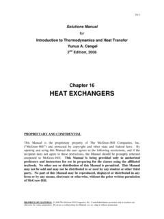
9 2008 The McGraw-Hill Companies, Inc. Limited distribution permitted only to teachers and educators for course preparation. If you are a student using this manual , you are using it without permission. 16-5 16-19 EES Prob. 16-18 is reconsidered. The effects of pipe conductivity and heat transfer coefficients on the thermal resistance of the heat exchanger are to be investigated. Analysis The problem is solved using EES, and the solution is given below. "GIVEN" k=380 [W/m-C] D_i= [m] D_o= [m] D_2= [m] h_i=700 [W/m^2-C] h_o=1400 [W/m^2-C] R_f_i= [m^2-C/W] R_f_o= [m^2-C/W] "ANALYSIS" R=1/(h_i*A_i)+R_f_i/A_i+ln(D_o/D_i)/(2*p i*k*L)+R_f_o/A_o+1/(h_o*A_o) L=1 [m] a unit length of the heat exchanger is considered" A_i=pi*D_i*L A_o=pi*D_o*L k [W/m-C] R [C/W] 10 400 [W/m-C]R [C/W] PROPRIETARY MATERIAL.
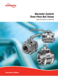
10 2008 The McGraw-Hill Companies, Inc. Limited distribution permitted only to teachers and educators for course preparation. If you are a student using this manual , you are using it without permission. 16-6 hi [W/m2-C] R [C/W] 500 550 600 650 700 750 800 850 900 950 1000 1050 1100 1150 1200 1250 1300 1350 1400 1450 1500 ho [W/m2-C] R [C/W] 1000 1050 1100 1150 1200 1250 1300 1350 1400 1450 1500 1550 1600 1650 1700 1750 1800 1850 1900 1950 2000 [W /m2-C]R [C/W] [W/m2-C]R [C/W] PROPRIETARY MATERIAL.