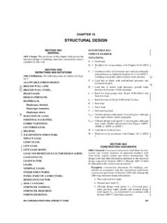
Transcription of CHAPTER 16 STRUCTURAL DESIGN - NCDOI - Home Page
1 CHAPTER 16 STRUCTURAL DESIGN User note: Code change proposals to this CHAPTER will be considered by the IBC STRUCTURAL Code Development Committee during the 2016 (Group B) Code Development Cycle. See explanation on page iv. In-situ load tests. The building official is authorized to require an engineering analysis or a load test, or both, of any construction whenever there is reason to question the safety of the construction for the intended occupancy. Engineering analysis and load tests shall be conducted in accordance with Section 1709 1708. Preconstruction load tests. Materials and methods of construction that are not capable of being designed by approved engineering analysis or that do not comply with the applicable referenced standards, or alternative test procedures in accordance with Section 1707, shall be load tested in accordance with Section 1710 1709.
2 SECTION 1608 SNOW LOADS Ground snow loads. The ground snow loads to be used in determining the DESIGN snow loads for roofs shall be determined in accordance with ASCE 7 or Figure for the contiguous United States and Table for Alaska North Carolina. Site-specific case studies shall be made in areas designated CS in Figure Ground snow loads for sites at elevations above the limits indicated in Figure and for all sites within the CS areas shall be approved. Ground snow load determination for such sites shall be based on an extreme value statistical analysis of data available in the vicinity of the site using a value with a 2-percent annual probability of being exceeded (50-year mean recurrence interval). Snow loads are zero for Hawaii, except in mountainous regions as approved by the building official. TABLE GROUND SNOW LOADS, pg, FOR ALASKAN LOCATIONS LOCATION POUNDS PER SQUARE FOOT LOCATION POUNDS PER SQUARE FOOT LOCATION POUNDS PER SQUARE FOOT Adak 30 Galena 60 Petersburg 150 Anchorage 50 Gulkana 70 St.
3 Paul Islands 40 Angoon 70 Homer 40 Seward 50 Barrow 25 Juneau 60 Shemya 25 Barter Island 35 Kenai 70 Sitka 50 Bethel 40 Kodiak 30 Talkeetna 120 Big Delta 50 Kotzebue 60 Unalakleet 50 Cold Bay 25 McGrath 70 Valdez 160 Cordova 100 Nenana 80 Whittier 300 Fairbanks 60 Nome 70 Wrangell 60 Fort Yukon 60 Palmer 50 Yakutat 150 For SI: 1 pound per square foot = kN/m2. FIGURE (DELETE THE FIGURE) GROUND SNOW LOADS, pg, FOR THE UNITED STATES (psf) FIGURE continued (DELETE THE FIGURE) GROUND SNOW LOADS, pg, FOR THE UNITED STATES (psf) In CS (hatched counties) areas, site-specific Case Studies are required to establish ground snow loads. Extreme local variations in ground snow loads in these areas preclude mapping at this scale. FIGURE (ADD NC FIGURE FROM 2012 NCBC Figure ) GROUND SNOW LOADS, pg, FOR THE STATE OF NORTH CAROLINA (psf) Ponding instability.
4 Susceptible bays of roofs shall be evaluated for ponding instability in accordance with Section of ASCE 7. SECTION 1609 WIND LOADS Protection of openings. In wind-borne debris regions, glazing in buildings shall be impact resistant or protected with an impact-resistant covering meeting the requirements of an approved impact-resistant standard or ASTM E 1996 and ASTM E 1886 referenced herein as follows: 1. Glazed openings located within 30 feet (9144 mm) of grade shall meet the requirements of the large missile test of ASTM E 1996. 2. Glazed openings located more than 30 feet (9144 mm) above grade shall meet the provisions of the small missile test of ASTM E 1996. Exceptions: 1. Wood STRUCTURAL panels with a minimum thickness of 7/16 inch ( mm) and maximum panel span of 8 feet (2438 mm) shall be permitted for opening protection in buildings with a mean roof height of 33 45 feet (10 058 mm) or less that are classified as a Group R-3 or R-4 occupancy.
5 Panels shall be precut so that they shall be attached to the framing surrounding the opening containing the product with the glazed opening. Panels shall be predrilled as required for the anchorage method and shall be secured with the attachment hardware provided. Attachments shall be designed to resist the components and cladding loads determined in accordance with the provisions of ASCE 7, with corrosion-resistant attachment hardware provided and anchors permanently installed on the building. Attachment in accordance with Table with corrosion-resistant attachment hardware provided and anchors permanently installed on the building is permitted for buildings with a mean roof height of 45 feet (13 716 mm) or less. where Vasd determined in accordance with Section does not exceed 140 mph (63 m/s). 2. Glazing in Risk Category I buildings, including greenhouses that are occupied for growing plants on a production or research basis, without public access shall be permitted to be unprotected.
6 3. Glazing in Risk Category II, III or IV buildings located over 60 feet (18 288 mm) above the ground and over 30 feet (9144 mm) above aggregate surface roofs located within 1,500 feet (458 m) of the building shall be permitted to be unprotected. Replace with NC maps and notes. FIGURE (1) ULTIMATE DESIGN WIND SPEEDS, vult, FOR RISK CATEGORY II BUILDINGS AND OTHER STRUCTURES Replace with NC maps and notes. FIGURE (2) ULTIMATE DESIGN WIND SPEEDS, vult, FOR RISK CATEGORY III AND IV BUILDINGS AND OTHER STRUCTURES Replace with NC maps and notes. FIGURE (3) ULTIMATE DESIGN WIND SPEEDS, vult, FOR RISK CATEGORY I BUILDINGS AND OTHER STRUCTURES For SI: 1 inch = mm. Source: National Weather Service, National Oceanic and Atmospheric Administration, Washington, DC. REPLACE FIG. WITH NC MAP AND NOTES [P] FIGURE 100-YEAR, 1-HOUR RAINFALL (INCHES) WESTERN UNITED STATES For SI: 1 inch = mm.
7 Source: National Weather Service, National Oceanic and Atmospheric Administration, Washington, DC. [P] FIGURE continued 100-YEAR, 1-HOUR RAINFALL (INCHES) CENTRAL UNITED STATES For SI: 1 inch = mm. Source: National Weather Service, National Oceanic and Atmospheric Administration, Washington, DC. [P] FIGURE continued 100-YEAR, 1-HOUR RAINFALL (INCHES) EASTERN UNITED STATES For SI: 1 inch = mm. Source: National Weather Service, National Oceanic and Atmospheric Administration, Washington, DC. [P] FIGURE continued 100-YEAR, 1-HOUR RAINFALL (INCHES) ALASKA For SI: 1 inch = mm. Source: National Weather Service, National Oceanic and Atmospheric Administration, Washington, DC. [P] FIGURE continued 100-YEAR, 1-HOUR RAINFALL (INCHES) HAWAII Ponding instability. Susceptible bays of roofs shall be evaluated for ponding instability in accordance with Section of ASCE 7.
8 Definitions. The following terms are defined in CHAPTER 2: BASE FLOOD. BASE FLOOD ELEVATION. BASEMENT. COASTAL A ZONE. COASTAL HIGH HAZARD AREA. DESIGN FLOOD. DESIGN FLOOD ELEVATION. DRY FLOODPROOFING. EXISTING CONSTRUCTION. EXISTING STRUCTURE. FLOOD or FLOODING. FLOOD DAMAGE-RESISTANT MATERIALS. FLOOD HAZARD AREA. FLOOD INSURANCE RATE MAP (FIRM). FLOOD INSURANCE STUDY. FLOODWAY. LOWEST FLOOR. SPECIAL FLOOD HAZARD AREA. START OF CONSTRUCTION. SUBSTANTIAL DAMAGE. SUBSTANTIAL IMPROVEMENT. Flood hazard documentation. The following documentation shall be prepared and sealed by a registered DESIGN professional and submitted to the building official: 1. For construction in flood hazard areas other than coastal high hazard areas or coastal A zones: The elevation of the lowest floor, including the basement, prior to further vertical construction.
9 As required by the lowest floor elevation inspection in Section and for the final inspection in Section For fully enclosed areas below the DESIGN flood elevation where provisions to allow for the automatic entry and exit of floodwaters do not meet the minimum requirements in Section of ASCE 24, construction documents shall include a statement that the DESIGN will provide for equalization of hydrostatic flood forces in accordance with Section of ASCE 24. For dry floodproofed nonresidential buildings, construction documents shall include a statement that the dry floodproofing is designed in accordance with ASCE 24. 2. For construction in coastal high hazard areas and coastal A zones: The elevation of the bottom of the lowest horizontal STRUCTURAL member prior to further vertical construction. as required by the lowest floor elevation inspection in Section and for the final inspection in Section Construction documents shall include a statement that the building is designed in accordance with ASCE 24, including that the pile or column foundation and building or structure to be attached thereto is designed to be anchored to resist flotation, collapse and lateral movement due to the effects of wind and flood loads acting simultaneously on all building components, and other load requirements of CHAPTER 16.
10 For breakaway walls designed to have a resistance of more than 20 psf ( kN/m2) determined using allowable stress DESIGN , construction documents shall include a statement that the breakaway wall is designed in accordance with ASCE 24. SECTION 1613 EARTHQUAKE LOADS Mapped acceleration parameters. The parameters SS and S1 shall be determined from the and 1-second spectral response accelerations shown on Figures (1) through (8). Where S1 is less than or equal to and SS is less than or equal to , the structure is permitted to be assigned Seismic DESIGN Category A. REPLACE FIGS. (x) WITH NC FIGURES. UPDATE LINES TO 2015 IBC. FIGURE (1) RISK-TARGETED MAXIMUM CONSIDERED EARTHQUAKE (MCER) GROUND MOTION RESPONSE ACCELERATIONS FOR THE CONTERMINOUS UNITED STATES OF SPECTRAL RESPONSE ACCELERATION (5% OF CRITICAL DAMPING), SITE CLASS B (continued) FIGURE (1) continued RISK-TARGETED MAXIMUM CONSIDERED EARTHQUAKE (MCER) GROUND MOTION RESPONSE ACCELERATIONS FOR THE CONTERMINOUS UNITED STATES OF SPECTRAL RESPONSE ACCELERATION (5% OF CRITICAL DAMPING), SITE CLASS B FIGURE (2) RISK-TARGETED MAXIMUM CONSIDERED EARTHQUAKE (MCER) GROUND MOTION RESPONSE ACCELERATIONS FOR THE CONTERMINOUS UNITED STATES OF 1-SECOND SPECTRAL RESPONSE ACCELERATION (5% OF CRITICAL DAMPING), SITE CLASS B FIGURE (2) continued RISK-TARGETED MAXIMUM CONSIDERED EARTHQUAKE (MCER)
