Transcription of Chapter 18 Introduction to Structural Steel - NAVY BMR
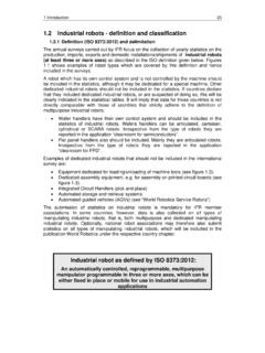
1 Chapter 18 Introduction to Structural Steel Topics Structural Steel Members Anchor Bolts Bearing Plates Columns Girders Beams Bar Joists Trusses Purlins, Girts, and Eave Struts To hear audio, click on the box. Overview This Chapter will give you a brief overview of Structural Steel . Structural Steel is used as the framework for many Steel structures such as industrial and commercial buildings, advanced base structures, and bridges. Many different pieces go into fabricating and erecting the framework for a Steel structure, and as a Seabee Steelworker, you must have a thorough knowledge of the various Structural members. We will discuss the most common names of the Steel members as well as how to fasten and secure the members to each other and to the concrete foundation they are built upon. We will also discuss where and how in the structure the Steel members are used.
2 Before any Structural Steel is fabricated or erected, a plan of action and sequence of events, or erection, needs to be set up. The plans, sequences, and required materials are predetermined by the engineering section and drawn up as a set of plans. This Chapter describes the basics of Structural Steel : the terminology, use of the members, methods of connection , and basic sequence of events during erection. NAVEDTRA 14250A18-1 Objectives When you have completed this Chapter , you will be able to do the following: 1. Describe the different types of Structural Steel members. 2. Describe the purpose and types of anchor bolts. 3. Describe the purpose and types of bearing plates. 4. Describe the purpose and types of columns. 5. Describe the purpose and types of girders. 6. Describe the purpose and types of beams. 7. Describe the purpose and types of bar joists. 8. Describe the purpose and types of trusses. 9. Describe the purpose and types of purlins, girts, and eave struts.
3 Prerequisites None NAVEDTRA 14250A18-2 This course map shows all of the chapters in Steelworker Basic. The suggested training order begins at the bottom and proceeds up. Skill levels increase as you advance on the course map. Introduction to Reinforcing Steel S T E E L W O R K E R B A S I C Introduction to Structural Steel Pre -Engineered Structures: Buildings, K-Spans, Towers and Antennas Rigging Wire rope Fiber Line Layout and Fabrication of Sheet metal and Fiberglass Duct Welding Quality Control Flux Cored Arc Welding-FCAW Gas -Metal Arc Welding-GMAW Gas -Tungsten Arc Welding-GTAW Shielded Metal Arc Welding-SMAW Plasma Arc Cutting Operations Soldering, Brazing, Braze Welding, Wearfacing Gas Welding Gas Cutting Introduction to Welding Basic Heat Treatment Introduction to Types and Identification of Metal NAVEDTRA 14250A18-3 Features of this Manual This manual has several features which make it easy to use online.
4 Figure and table numbers in the text are italicized. The figure or table is either next to or below the text that refers to it. The first time a glossary term appears in the text, it is bold and italicized. When your cursor crosses over that word or phrase, a popup box displays with the appropriate definition. Audio and video clips are included in the text, with an italicized instruction telling you where to click to activate it. Review questions that apply to a section are listed under the Test Your Knowledge banner at the end of the section. Select the answer you choose. If the answer is correct, you will be taken to the next section heading. If the answer is incorrect, you will be taken to the area in the Chapter where the information is for review. When you have completed your review, select anywhere in that area to return to the review question. Try to answer the question again. Review questions are included at the end of this Chapter .
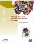
5 Select the answer you choose. If the answer is correct, you will be taken to the next question. If the answer is incorrect, you will be taken to the area in the Chapter where the information is for review. When you have completed your review, select anywhere in that area to return to the review question. Try to answer the question again. NAVEDTRA Structural Steel MEMBERS As a Steelworker, you will use various Structural members manufactured in a wide variety of cross section shapes and sizes. Figure 18-1 shows many of these shapes. The three most common types of Structural members are the W-shape (wide flange), the S-shape (American Standard I-beam), and the C-shape (American Standard channel). These three types are identified by the nominal depth, in inches, along the web and the weight per foot of length, in pounds. As an example, a W 12 x 27 indicates a W- shape (wide flange) with a web 12 inches deep and a weight of 27 pounds per linear foot.
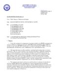
6 Figure 18-2 shows the cross-sectional views of the W-, S-, and C- shapes. The difference between the W-shape and the S-shape is in the design of the inner surfaces of the flange. The W-shape has parallel inner and outer flange surfaces with a constant thickness, while the S-shape has a slope of approximately 17 on the inner flange surfaces. The C-shape is similar to the S-shape in that its inner flange surface is also sloped approximately 17 . Figure 18-1 Structural shapes and designations. NAVEDTRA 14250A18-5 Terminology You need to know the industry standard names for every Structural member you will be using to prevent miscommunications between you and the other members on site, so we will discuss the Structural members names and some of their characteristics and uses. W-Shape The W shape is a Structural member whose cross section forms the letter H and is the most widely used Structural member.
7 It is designed so that its flanges provide strength in a horizontal plane, while the web gives strength in a vertical plane. W-shapes are used as beams, columns, and truss members, and in other load-bearing applications. Bearing Pile The bearing pile (HP -shape) is almost identical to the W-shape. The only difference is that the flange thickness and web thickness of the bearing pile are equal, whereas the W- shape has different web and flange thicknesses. S-Shape The S- shape (American Standard I-beam) is distinguished by its cross section being shap ed like the letter I. S-shapes are used less frequently than W-shapes since the S-shapes possess less strength and are less adaptable than W-shapes. Figure 18-2 Closer look at the W, S, and C Structural members. NAVEDTRA C-Shape The C- shape (American Standard channel) has a cross section somewhat similar to the letter C. It is especially useful in locations where a single flat face without outstanding flanges on one side is required.
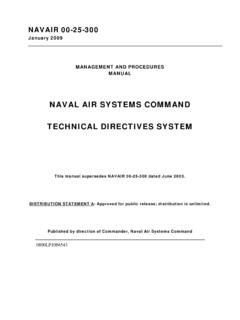
8 The C-shape is not very efficient for a beam or column when used alone. However, efficient built-up members may be constructed of channels assembled together with other Structural shapes and connected by rivets or welds. Angle An angle is a Structural shape whose cross section resembles the letter L. Two types, as illustrated in Figure 18-3, are commonly used: an equal-leg angle and an unequal-leg angle. The angle is identified by the dimension and thickness of its legs, for example, angle 6 inches x 4 inches x 1/2 inch. The dimension of the legs should be obtained by measuring along the outside of the backs of the legs. When an angle has unequal legs, the dimension of the wider leg is given first, as in the example just cited. The third dimension applies to the thickness of the legs, which always have equal thickness. Angles may be used in combinations of two or four to form main members. A single angle may also be used to connect main parts together.
9 Plate Steel plate is a Structural shape whose cross section is in the form of a flat rectangle. Generally, a main point to remember about plate is that it has a width of greater than 8 inches and a thickness of 1/4 inch or greater. Plates are generally used as connections between other Structural members or as component parts of built -up Structural members. Plates cut to specific sizes may be obtained in widths ranging from 8 inches to 120 inches or more, and in various thicknesses. The edges of these plates may be cut by shears (sheared plates) or be rolled square (universal mill plates). Frequently, p lates are referred to by their thickness and width in inches, as plate 1/2 inch x 24 inches. The length in all cases is given in inches. Note in Figure 18-4 that 1 cubic foot of Steel weighs 490 pounds. This weight divided by 12 gives you , which is the weight (in pounds) of a Steel plate 1 foot square and 1 inch thick.
10 The fractional portion is normally dropped and 1-inch plate is called a 40-pound plate. In practice, you may hear plate referred to by its approximate weight per square foot for a specified thickness. An example is 20-pound plate, which indicates a 1/2-inch plate. (Refer again to Figure 18-4). Figure 18-3 Angles. NAVEDTRA 14250A18-7 The designations generally used for flat Steel have been established by the American Iron and Steel Institute (AISI). Flat Steel is designated as bar, strip, sheet, or plate, according to the thickness of the material, the width of the material, and (to some extent) the rolling process to which it was subjected. Table 18-1 shows the designations usually used for hot -rolled carbon steels. These terms are somewhat flexible and in some cases may overlap Figure 18-4 Weight and thickness of Steel plate. NAVEDTRA 14250A18-8 Tab le 18 -1 Plate, B ar, Strip, and Sheet Designation.