Transcription of CHAPTER 2 DIGITAL MODULATION 2.1 INTRODUCTION
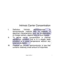
1 1 CHAPTER 2 DIGITAL MODULATION INTRODUCTION Referring to Equation ( ), if the information signal is DIGITAL and the amplitude (lV of the carrier is varied proportional to the information signal, a digitally modulated signal called amplitude shift keying (ASK) is produced. If the frequency (f) is varied proportional to the information signal, frequency shift keying (FSK) is produced, and if the phase of the carrier (0) is varied proportional to the information signal, phase shift keying (PSK) is produced. If both the amplitude and the phase are varied proportional to the information signal, quadrature amplitude MODULATION (QAM) results. ASK, FSK, PSK, and QAM are all forms of DIGITAL MODULATION : ( ) Figure 2-1 shows a simplified block diagram for a DIGITAL MODULATION system. 2 In the transmitter, the precoder performs level conversion and then encodes the incoming data into groups of bits that modulate an analog carrier.)
2 The modulated carrier is shaped (filtered), amplified, and then transmitted through the transmission medium to the receiver. The transmission medium can be a metallic cable, optical fiber cable, Earth's atmosphere, or a combination of two or more types of transmission systems. In the receiver, the incoming signals are filtered, amplified, and then applied to the demodulator and decoder circuits, which extracts the original source information from the modulated carrier. The clock and carrier recovery circuits recover the analog carrier and DIGITAL timing (clock) signals from the incoming modulated wave since they are necessary to perform the de- MODULATION process. FIGURE 2-1 Simplified block diagram of a DIGITAL radio system. 3 2-2 INFORMATION CAPACITY, BITS, BIT RATE, BAUD, AND MARY ENCODING 2-2-1 Information Capacity, Bits, and Bit Rate I B x t ( ) where I= information capacity (bits per second) B = bandwidth (hertz) t = transmission time (seconds) From Equation 2-2, it can be seen that information capacity is a linear function of bandwidth and transmission time and is directly proportional to both.
3 If either the bandwidth or the transmission time changes, a directly proportional change occurs in the information capacity. The higher the signal-to-noise ratio, the better the performance and the higher the information capacity. Mathematically stated, the Shannon limit_for information capacity is ( ) or ( ) where I = information capacity (bps) B = bandwidth (hertz) NS= signal-to-noise power ratio (unitless) 4 For a standard telephone circuit with a signal-to-noise power ratio of 1000 (30 dB) and a bandwidth of kHz, the Shannon limit for information capacity is I = ( )(2700) log10 (1 + 1000) = kbps Shannon's formula is often misunderstood. The results of the preceding example indicate that kbps can be propagated through a communications channel. This may be true, but it cannot be done with a binary system.
4 To achieve an information transmission rate of kbps through a channel, each symbol transmitted must contain more than one bit. 2-2-2 M-ary Encoding M-ary is a term derived from the word binary. M simply represents a digit that corresponds to the number of conditions, levels, or combinations possible for a given number of binary variables. For example, a DIGITAL signal with four possible conditions (voltage levels, frequencies, phases, and so on) is an M-ary system where M = 4. If there are eight possible conditions, M = 8 and so forth. The number of bits necessary to produce a given number of conditions is expressed mathematically as MN2log= ( ) where N = number of bits necessary M = number of conditions, levels, or combinations 5 possible with N bits Equation 2-5 can be simplified and rearranged to express the number of conditions possible with N bits as 2N= M ( ) For example, with one bit, only 21 = 2 conditions are possible.
5 With two bits, 22 = 4 conditions are possible, with three bits, 23 = 8 conditions are possible, and so on. 2-2-3 Baud and Minimum Bandwidth Baud refers to the rate of change of a signal on the transmission medium after encoding and MODULATION have occurred. Hence, baud is a unit of transmission rate, MODULATION rate, or symbol rate and, therefore, the terms symbols per second and baud are often used interchangeably. Mathematically, baud is the reciprocal of the time of one output signaling element, and a signaling element may represent several information bits. Baud is expressed as baud = st1 ( ) where baud = symbol rate (baud per second) ts = time of one signaling element (seconds) 6 The minimum theoretical bandwidth necessary to propagate a signal is called the minimum Nyquist bandwidth or sometimes the minimum Nyquist frequency.
6 Thus, fb = 2B, where fb is the bit rate in bps and B is the ideal Nyquist bandwidth. The relationship between bandwidth and bit rate also applies to the opposite situation. For a given bandwidth (B), the highest theoretical bit rate is 2B. For example, a standard telephone circuit has a bandwidth of approximately 2700 Hz, which has the capacity to propagate 5400 bps through it. However, if more than two levels are used for signaling (higher-than-binary encoding), more than one bit may be transmitted at a time, and it is possible to propagate a bit rate that exceeds 2B. Using multilevel signaling, the Nyquist formulation for channel capacity is fb = B log2 M ( ) where fb = channel capacity (bps) B = minimum Nyquist bandwidth (hertz) M = number of discrete signal or voltage levels Equation can be rearranged to solve for the minimum bandwidth necessary to pass M-ary digitally modulated carriers B = Mfb2log ( ) 7 If N is substituted for log2 M, Equation reduces to B = Nfb ( ) where N is the number of bits encoded into each signaling element.
7 In addition, since baud is the encoded rate of change, it also equals the bit rate divided by the number of bits encoded into one signaling element. Thus, Baud = Nfb ( ) By comparing Equation with Equation the baud and the ideal minimum Nyquist bandwidth have the same value and are equal to the bit rate divided by the number of bits encoded. 2-3 AMPLITUDE-SHIFT KEYING The simplest DIGITAL MODULATION technique is amplitude-shift keying (ASK), where a binary information signal directly modulates the amplitude of an analog carrier. ASK is similar to standard amplitude MODULATION except there are only two output amplitudes possible. Amplitude-shift keying is sometimes called DIGITAL amplitude MODULATION (DAM). 8 Mathematically, amplitude-shift keying is ( ) where vask(t) = amplitude-shift keying wave vm(t) = DIGITAL information (modulating) signal (volts) A/2 = unmodulated carrier amplitude (volts) c = analog carrier radian frequency (radians per second, 2 fct) In Equation , the modulating signal [vm(t)] is a normalized binary waveform, where + 1 V = logic 1 and -1 V = logic 0.
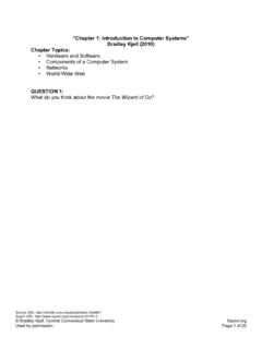
8 Therefore, for a logic 1 input, vm(t) = + 1 V, Equation reduces to and for a logic 0 input, vm(t) = -1 V, Equation reduces to Thus, the modulated wave vask(t), is either A cos( c t) or 0. Hence, the carrier is either "on"or "off," which is why amplitude-shift keying is sometimes referred to as on-off keying(OOK). 9 Figure 2-2 shows the input and output waveforms from an ASK modulator. From the figure, it can be seen that for every change in the input binary data stream, there is one change in the ASK waveform, and the time of one bit (tb) equals the time of one analog signaling element (t,). B = fb /1 = fb baud = fb /1 = fb FIGURE 2-2 DIGITAL amplitude MODULATION : (a) input binary; (b) output DAM waveform The entire time the binary input is high, the output is a constant-amplitude, constant-frequency signal, and for the entire time the binary input is low, the carrier is off.
9 The rate of change of the ASK waveform (baud) is the same as the rate of change of the binary input (bps). Example 2-1 Determine the baud and minimum bandwidth necessary to pass a 10 kbps binary signal using amplitude shift keying. 10 Solution For ASK, N = 1, and the baud and minimum bandwidth are determined from Equations and , respectively: B = 10,000 / 1 = 10,000 baud = 10, 000 /1 = 10,000 The use of amplitude-modulated analog carriers to transport DIGITAL information is a relatively low-quality, low-cost type of DIGITAL MODULATION and, therefore, is seldom used except for very low-speed telemetry circuits. 2-4 FREQUENCY-SHIFT KEYING FSK is a form of constant-amplitude angle MODULATION similar to standard frequency MODULATION (FM) except the modulating signal is a binary signal that varies between two discrete voltage levels rather than a continuously changing analog waveform.
10 Consequently, FSK is sometimes called binary FSK (BFSK). The general expression for FSK is ( ) where vfsk(t) = binary FSK waveform Vc = peak analog carrier amplitude (volts) fc = analog carrier center frequency (hertz) f = peak change (shift) in the analog carrier frequency 11 (hertz) vm(t) = binary input (modulating) signal (volts) From Equation , it can be seen that the peak shift in the carrier frequency ( f) is proportional to the amplitude of the binary input signal (vm[t]), and the direction of the shift is determined by the polarity. The modulating signal is a normalized binary waveform where a logic 1 = + 1 V and a logic 0 = -1 V. Thus, for a logic l input, vm(t) = + 1, Equation can be rewritten as For a logic 0 input, vm(t) = -1, Equation becomes With binary FSK, the carrier center frequency (fc) is shifted (deviated) up and down in the frequency domain by the binary input signal as shown in Figure 2-3.