Transcription of Chapter 2 – Dry Extended Detention Basin
1 VDOT BMP Design Manual of Practice i Chapter 2 Dry Extended Detention Basin Chapter 2 Dry Extended Detention Basin TABLE OF CONTENTS Overview of Practice .. 1 Site Constraints and Siting of the facility .. 2 Minimum Drainage Area .. 2 Maximum Drainage Area .. 5 Separation Distances .. 5 Site Slopes .. 5 Site Soils .. 6 Rock .. 6 Existing Utilities .. 6 Karst .. 6 Wetlands .. 6 Upstream Sediment Considerations .. 7 Floodplains .. 7 Basin Location .. 7 General Design Guidelines .. 8 Foundation and Embankment Material .. 8 Outfall Piping .. 8 Embankment .. 8 Embankment 9 Prevention of Short-Circuiting.
2 9 Ponded Depth .. 9 Principal Spillway Design .. 9 Emergency Spillway Stabilization .. 10 Fencing .. 10 Sediment Forebays .. 10 Discharge Flows .. 10 Design Process .. 11 Step 1. Compute the Required Water Quality Volume .. 11 Step 2. Estimate the Volume Required for Mitigation of Post-Development Runoff Peaks to Equal or Less than Pre-Development Levels .. 13 Step 3. Development of Runoff Hydrographs .. 17 Table of Contents VDOT BMP Design Manual of Practice ii Chapter 2 Dry Extended Detention Basin Step 4. Development of Storage Versus Elevation Data .. 19 Step 5. Design of the Water Quality Control Orifice.
3 20 Step 6. Design of the Principal Spillway .. 22 Step 6A. Size Basin Outfall Culvert .. 22 Step 6B. Design the 2-Year Control 25 Step 6C. Design the 10-Year Control Outlet .. 28 Step 6D. Evaluate the Performance of the Principal Spillway Under 100-Year Runoff Conditions .. 33 Step 6E. Verify Target Draw Down Time for Water Quality Volume .. 33 Step 7. Design of the Emergency Spillway .. 35 Step 8. Provision for Seepage Control .. 41 Step 9. Embankment Design .. 42 Step 10. Buoyancy Calculation .. 44 Step 11. Design of Sediment Forebays .. 46 Step 12. 49 Table of Contents VDOT BMP Design Manual of Practice iii Chapter 2 Dry Extended Detention Basin LIST OF TABLES Table Hydrologic Characteristics of Example Project Site.
4 11 Table Peak Rates of Runoff (cfs) .. 11 Table Rainfall Regression Constants for Montgomery County .. 15 Table Basin Storage Versus Elevation Data .. 20 Table Preliminary Stage Discharge Relationship .. 27 Table Final Stage Discharge Relationship .. 31 Table 100-Year Post-Development Runoff Parameters .. 36 Table Armored Emergency Spillway Parameters .. 38 Table Exit Channel Permissible Velocities .. 39 Table Summary of Pond Inflow Points .. 47 LIST OF FIGURES Figure Schematic Dry Extended Detention Basin Plan 2 Figure DCR Recommended Outlet Configuration 1 for the Control of Trash, Sediment and Debris (Virginia Stormwater Management Handbook,1999, Et seq.)
5 3 Figure DCR Recommended Outlet Configuration 2 for the Control of Trash, Sediment and Debris (Virginia Stormwater Management Handbook,1999, Et seq.).. 4 Figure DCR Recommended Outlet Configuration 3 for the Control of Trash, Sediment and Debris (Virginia Stormwater Management Handbook,1999, Et seq.).. 5 Figure Modified Rational Runoff Hydrographs .. 13 Figure Graphical Determination of Critical Rainfall Intensity Duration .. 14 Figure Modified Rational Hydrograph Shape .. 17 Figure 2-Year Post-Development Modified Rational Hydrograph .. 18 Figure 10-Year Post-Development Modified Rational Hydrograph.
6 18 Figure Basin Storage Versus Elevation Curve .. 20 Figure Culvert Design Chart (FHWA, 2001) .. 24 Figure Preliminary Routing Results 2-Year Inflow Hydrograph .. 28 Figure VDOT SWM-DR Inlet Top (Metal) .. 29 Figure VDOT SWM-1 Riser .. 29 Figure Routing Results 10-Year Inflow Hydrograph .. 32 Figure Water Quality Draw Down Calculator .. 33 Figure Verification of Water Quality Draw .. 34 Figure Profile and Cross Section of Typical Vegetated Emergency 35 Figure Design Data for Earth Spillways .. 37 Figure Schematic Illustration of Principal and Emergency.
7 40 Figure Typical Concrete Cradle for Minimization of Piping Along .. 41 Figure Typical Cutoff Trench Configuration .. 43 Figure VDOT SWM-1 Side View .. 44 Figure Plan View Sediment Forebay 1 .. 48 Figure Cross-Section View Sediment Forebay 1 .. 49 Figure USDA Plant Hardiness Zones .. 50 - Overview of Practice VDOT BMP Design Manual of Practice 1of 50 Chapter 2 Dry Extended Detention Basin Overview of Practice A dry Extended Detention Basin is defined as an impoundment which temporarily detains runoff and releases that runoff at a controlled rate over a specified period of time.
8 By definition, Extended dry Detention basins are dry structures during non-precipitation periods. Extended dry Detention basins are capable of providing water quality improvement, downstream flood control, channel erosion control, and mitigation of post-development runoff to pre-development levels. The primary mechanism by which a dry Extended Detention facility improves runoff quality is through the gravitational settling of pollutants. Extended dry Detention basins are most effective as water quality improvement practices when the impervious cover of their total contributing drainage area ranges between 22 and 37%.
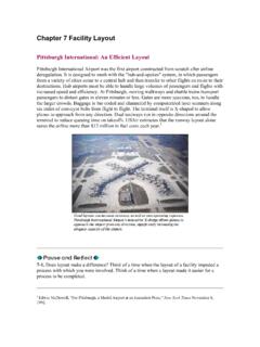
9 Additionally, as shown, Extended dry Detention facilities should be designed to provide 30-hour drawdown storage for twice the site s computed water quality volume (2 X WQV), equivalent to a total of one inch of runoff from the project site s impervious area. Figure presents the schematic layout of a dry Extended Detention Basin presented in the Virginia Stormwater Management Handbook (DCR, 1999, Et seq.). Of note is that the low flow rip rap lined channel has been removed from the drawing. Per Instructional and Informational Memorandum IIM-LD-195 under Post Development Stormwater Management , Section , this channel is not recommended due to maintenance concerns.
10 - Site Constraints and Siting of the facility VDOT BMP Design Manual of Practice 2of 50 Chapter 2 Dry Extended Detention Basin Figure Schematic Dry Extended Detention Basin Plan View (Virginia Stormwater Management Handbook, 1999, Et seq.) Site Constraints and Siting of the facility In addition to the impervious cover in the contributing drainage area, the designer must consider additional site constraints when the implementation of a dry Extended Detention Basin is proposed. These constraints are discussed as follows. Minimum Drainage Area The minimum drainage area contributing to a dry Extended Detention facility is not restricted.