Transcription of Chapter 2: Parametric Analysis in ANSYS Workbench Using ...
1 Chapter 2: Parametric Analysis in ANSYS Workbench Using ANSYSF luentThis tutorial is divided into the following Problem Setup and IntroductionThis tutorial illustrates Using an ANSYS Fluent fluid flow system in ANSYS Workbench to set up andsolve a three-dimensional turbulent fluid flow and heat transfer problem in an automotive heating,ventilation, and air conditioning (HVAC) duct system. ANSYS Workbench uses parameters and designpoints to allow you to run optimization and what-if scenarios. You can define both input and outputparameters in ANSYS Fluent that can be used in your ANSYS Workbench project.
2 You can also defineparameters in other applications including ANSYS DesignModeler and ANSYS CFD-Post. Once you havedefined parameters for your system, a Parameters cell is added to the system and the Parameter Setbus bar is added to your project. This tutorial is designed to introduce you to the Parametric analysisutility available in ANSYS tutorial starts with a Fluid Flow (Fluent) Analysis system with pre-defined geometry and meshcomponents. Within this tutorial, you will redefine the geometry parameters created in ANSYS Design-Modeler by adding constraints to the input parameters.
3 You will use ANSYS Fluent to set up and solvethe CFD defining the problem set-up, you will also learn to define input parameters inANSYS Fluent. The tutorial will also provide information on how to create output parameters in tutorial demonstrates how to do the following: Add constraints to the ANSYS DesignModeler input parameters. Create an ANSYS Fluent fluid flow Analysis system in ANSYS Workbench . Set up the CFD simulation in ANSYS Fluent, which includes: Setting material properties and boundary conditions for a turbulent forced convection problem. Defining input parameters in Fluent Define output parameters in CFD-Post Create additional design points in ANSYS Workbench .
4 Run multiple CFD simulations by updating the design - SAS IP, Inc. All rights reserved. - Contains proprietary and confidential informationof ANSYS , Inc. and its subsidiaries and affiliates. Analyze the results of each design point project in ANSYS CFD-Post and ANSYS mesh and solution settings for this tutorial are designed to demonstrate a basic paramet-erization simulation within a reasonable solution time-frame. Ordinarily, you would use addi-tional mesh and solution settings to obtain a more accurate PrerequisitesThis tutorial assumes that you are already familiar with the ANSYS Workbench interface and its projectworkflow (for example, ANSYS DesignModeler, ANSYS Meshing, ANSYS Fluent, and ANSYS CFD-Post).
5 This tutorial also assumes that you have completed Introduction to Using ANSYS Fluent in ANSYSW orkbench: Fluid Flow and Heat Transfer in a Mixing Elbow (p. 1), and that you are familiar with theANSYS Fluent graphical user interface. Some steps in the setup and solution procedure will not beshown Problem DescriptionIn the past, evaluation of vehicle air conditioning systems was performed Using prototypes and testingtheir performance in test labs. However, the design process of modern vehicle air conditioning (AC)systems improved with the introduction of Computer Aided Design (CAD), Computer Aided Engineering(CAE) and Computer Aided Manufacturing (CAM).
6 The AC system specification will include minimumperformance requirements, temperatures, control zones, flow rates, and so on. Performance testingusing CFD may include fluid velocity (air flow), pressure values, and temperature distribution. UsingCFD enables the Analysis of fluid through very complex geometry and boundary part of the Analysis , a designer can change the geometry of the system or the boundary conditionssuch as the inlet velocity, flow rate, and so on, and view the effect on fluid flow patterns. This tutorialillustrates the AC design process on a representative automotive HVAC system consisting of both anevaporator for cooling and a heat exchanger for heating requirements.
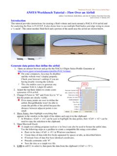
7 This HVAC system is symmetric,so the geometry has been simplified Using a plane of symmetry to reduce computation - SAS IP, Inc. All rights reserved. - Contains proprietary and confidential informationof ANSYS , Inc. and its subsidiaries and Analysis in ANSYS Workbench Using ANSYS FluentFigure : Automotive HVAC System75 Release - SAS IP, Inc. All rights reserved. - Contains proprietary and confidential informationof ANSYS , Inc. and its subsidiaries and DescriptionFigure : HVAC System Valve Location DetailsFigure : Automotive HVAC System (p. 75) shows a representative automotive HVAC systemhas three valves (as shown in Figure : HVAC System Valve Location Details (p.))
8 76)), which control theflow in the HVAC three valves control: Flow over the heat exchanger coils Flow towards the duct controlling the flow through the floor vents Flow towards the front vents or towards the windshieldAir enters the HVAC system at 310 K with a velocity of m/sec through the air inlet and passes tothe evaporator and then, depending on the position of the valve controlling flow to the heat exchanger,flows over or bypasses the heat exchanger. Depending on the cooling and heating requirements, eitherthe evaporator or the heat exchanger would be operational, but not both at the same time.
9 The positionof the other two valves controls the flow towards the front panel, the windshield, or towards the motion of the valves is constrained. The valve controlling flow over the heat exchanger variesbetween 25 and 90 .The valve controlling the floor flow varies between 20 and 60 .The valve con-trolling flow towards front panel or windshield varies between 15 and 175 .The evaporator load is about 200 W in the cooling cycle. The heat exchanger load is about 150 tutorial illustrates the easiest way to analyze the effects of the above parameters on the flow pat-tern/distribution and the outlet temperature of air (entering the passenger cabin).
10 Using the parametricRelease - SAS IP, Inc. All rights reserved. - Contains proprietary and confidential informationof ANSYS , Inc. and its subsidiaries and Analysis in ANSYS Workbench Using ANSYS Fluentanalysis capability in ANSYS Workbench , a designer can check the performance of the system at variousdesign : Flow Pattern for the Cooling Setup and SolutionTo help you quickly identify graphical user interface items at a glance and guide you through the stepsof setting up and running your simulation, the ANSYS Fluent Tutorial Guide uses several type styles andmini flow charts.